Pacing lead in an extended area of a heart cavity, implantable by over the wire technique in the deep coronary network

a deep coronary network and extended area technology, applied in the field of active implantable medical devices, can solve the problems of large diameter, difficult to concurrently implant two leads in the coronary venous system, and limitations described above on the fineness of leads, so as to facilitate the transmission of forces, reduce the thickness of the electrically insulating exterior layer and reduce the diameter of the hollow tubular extension

Active Publication Date: 2016-07-19
SORIN CRM
View PDF12 Cites 7 Cited by
  • Summary
  • Abstract
  • Description
  • Claims
  • Application Information

AI Technical Summary

Benefits of technology

[0022]One advantage of the present invention lies in the fact that, in the vein, the hollow tubular extension is not subject to the risk of abrasion with another device (including another lead), unlike the remaining portion of the lead body in the right atrium or the intravenous path. Consequently, the thickness of the electrically insulating exterior layer of the hollow tubular extension can be significantly reduced, thus contributing to the overall reduction in diameter of the hollow tubular extension.
[0023]Yet another aspect of the present invention is that the hollow tubular extension has on its outer surface a peripheral electrical conductor, which is isolated with the exception of a plurality of denuded areas forming a respective plurality of electrodes electrically connected together via the peripheral conductor. The denuded areas forming electrodes are advantageously preferably a plurality of denuded areas spaced apart yet divided into one or several active stimulation regions. These electrodes are designed to come into contact with the wall of a target-vein of the coronary network for the application, simultaneously in several places, of stimulation pulses on the wall of the epicardium.
[0024]It should be understood that it is the conductor itself that is used as an electrode (by the denuded areas which expose the underlying conductor), unlike conventional leads which typically use applied electrodes, structurally distinct from the conductor that connects them to the generator coupled to the lead.
[0025]In addition, construction and materials of the hollow tubular extension are chosen so as to give the latter the properties required to enable progression in the coronary venous system after being threaded over a guide wire (the OTW technique), namely: an axial stiffness sufficient to facilitate the transmission of forces from end to end (the so-called pushability property), distal flexibility, and a low friction coefficient of an internal central lumen for a good sliding on the guide wire (the so-called trackability).
[0026]In one embodiment, the configuration of the lead according to the present invention allows the hollow tubular extension to be introduced in a first vein (the “go” vein), then through an anastomosis to and in a second vein (the “return” vein). Distal anastomosis in the coronary venous system has indeed very frequently been found, typically 60 to 80% of the patient population. In this regard, at the end of some veins there is a passage to another vein, and thus a possibility of communication between two distinct veins at the anastomosis, via their respective distal ends.
[0027]The distribution of the electrodes (the denuded areas) of the hollow tubular extension may be chosen such that the electrodes are grouped into two separate sets, forming two separate active regions, one for the definition of the stimulation sites in the “go” vein and the other for the definition of the stimulation sites in the “return” vein. These two sets of electrodes are separated by an intermediate isolated region corresponding to the most distal parts of the “go” vein, the region of the anastomosis, and the most distal parts of the “return” vein.

Problems solved by technology

In this regard, recent studies show that it is very difficult to concurrently implant two leads in the coronary venous system.
However, these leads have a relatively large diameter of at least about 4 French (1.33 mm), due to the complexity of the components and of the connections necessary for the selection of the electrodes for electronic repositioning.
The limitations described above on the fineness of the lead is thus present.
Furthermore, the relative position of the selected pairs of electrodes is very limited, these pairs of electrodes being also necessarily positioned in the coronary vein, usually the posterolateral vein.

Method used


Image

  • Pacing lead in an extended area of a heart cavity, implantable by over the wire technique in the deep coronary network
  • Pacing lead in an extended area of a heart cavity, implantable by over the wire technique in the deep coronary network
  • Pacing lead in an extended area of a heart cavity, implantable by over the wire technique in the deep coronary network

Examples


Embodiment Construction

[0056]With reference to the drawings FIGS. 1-7, preferred embodiments of a lead in accordance with the present invention will now be described.

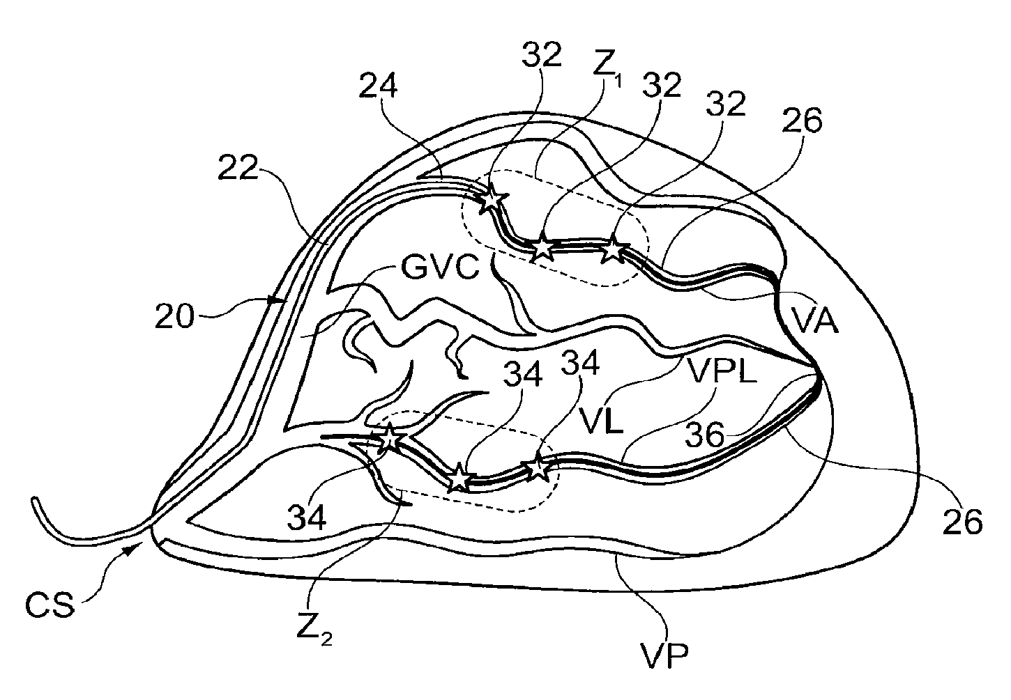
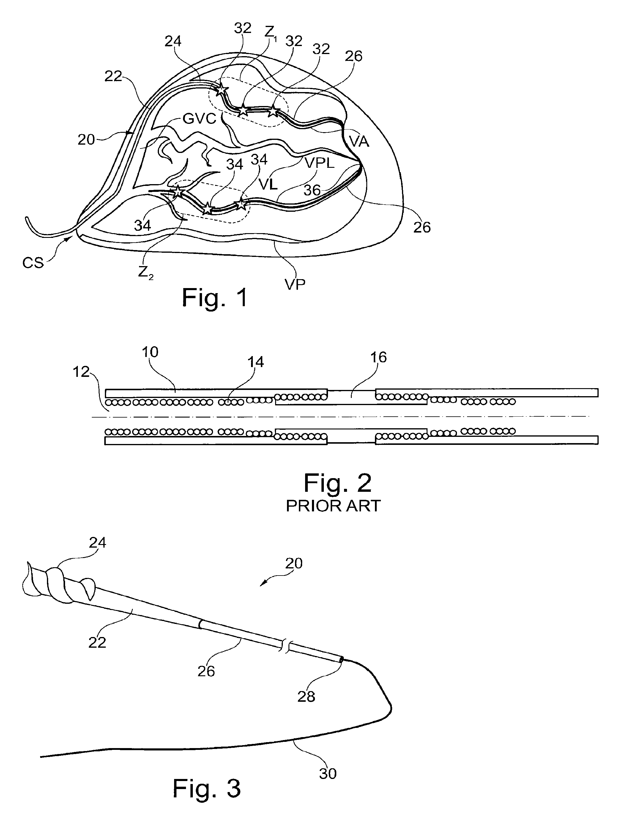
[0057]FIG. 1 generally illustrates a patient's myocardium and major vessels of the coronary network, in which a lead 20 was introduced to stimulate the left ventricle. Lead 20 is implanted in the intracardiac coronary venous system via the superior vena cava, right atrium and the input of the coronary sinus vein CS. The coronary venous system then develops into several branches from the great cardiac vein GVC, these veins branches including the posterolateral vein VPL, the lateral vein VL, the anterolateral vein VA and the posterior vein VP.

[0058]FIG. 2 illustrates in cross section and schematically, in the region of the stimulation electrode, the structure of a conventional prior art pacing lead for implantation in the coronary venous system. This conventional construction comprises an electrically insulating lead body 10, with a central lum...


PUM

PropertyMeasurementUnit
diameteraaaaaaaaaa
diameteraaaaaaaaaa
surface areaaaaaaaaaaa

Abstract

A pacing lead having a lead body comprising a hollow sheath by a first lumen and an extension body extending from the lead body, the extension body having a proximal end and a distal end, the distal end having an active lead region. The extension is traversed by a second lumen, the second lumen communicating with the first lumen of the lead body so as to receive a guide wire for the implantation of the lead. The extension has an outside diameter of between 1 and 3 French. The extension distal end comprises at least one electrically isolated peripheral conductor electrically insulated except for at least two denuded areas on an outer surface of the conductor to contact a wall of a target vein, so as to form a network of stimulation electrodes electrically connected together. The lead body proximal end includes an electrical connection for the peripheral conductor.

Description

CROSS-REFERENCE TO RELATED PATENT APPLICATIONS[0001]This application is a continuation of U.S. application Ser. No. 13 / 623,400, filed on Sep. 20, 2012, which claims the benefit of and priority to French Patent Application No. 11 / 58417, filed Sep. 21, 2011, both of which are hereby incorporated by reference herein in their entireties.BACKGROUND[0002]The present invention relates to “active implantable medical devices” as defined by the Jun. 20, 1990 directive 90 / 395 / CEE of the European Community Council, more specifically implanted devices that continuously monitor a patient's cardiac rhythm and deliver if and as necessary to the patient's heart electrical pulses for stimulation (pacing), cardiac resynchronization, cardioversion and / or defibrillation, and more specifically to cardiac pacing leads to be implanted in the coronary network of the heart to allow stimulation of a left or right heart cavity, i.e., a ventricle or atrium.[0003]Unlike the right heart cavities for which it is s...

Claims


Application Information

Patent Timeline
Patent Type & Authority Patents(United States)
IPC IPC(8): A61N1/00H01R43/16A61N1/05
CPCA61N1/0573A61N1/056H01R43/16A61N2001/0585Y10T29/49204
Inventor OLLIVIER, JEAN-FRANCOIS
Owner SORIN CRM
Why Eureka
Try Eureka