Segmented attenuator with glitch reduction

a segmented attenuator and glitch reduction technology, applied in the field of electronic circuits, can solve the problems of binary-weighted dsas suffering from switching transients (glitches), unwanted detection errors, and dsa performance degradation, and achieve the effect of reducing the switching transients (glitches) and minimizing the amplitude of glitches

Active Publication Date: 2016-07-19
PSEMI CORP
View PDF1 Cites 12 Cited by
  • Summary
  • Abstract
  • Description
  • Claims
  • Application Information

AI Technical Summary

Benefits of technology

[0014]The invention is a method and circuit for significantly reducing the switching transients (glitches) (both positive and negative) of digital step attenuators (DSA's) by employing a segmented DSA architecture that combines thermometer and binary coded stages. This approach reduces the number of attenuator stages switching at the same time and thus minimizes any glitch amplitude.
[0015]A segmented architecture reduces the number of simultaneously switched attenuators, but the total number of stages is increased. Thus, while embodiments of a segmented DSA may be realized with the same type of attenuator stages as in a purely binary-weighted DSA, the integrated circuit die (“chip”) area may increase. Accordingly, in one embodiment, simple L-pad attenuators, each consisting of only four components, are combined in a resistor ladder network, as opposed to the series cascade of conventional attenuator stages, which typically contain six components per stage. The resistor ladder configuration thus aids in alleviating the physical constraints imposed by a segmented architecture.

Problems solved by technology

This asymmetrical switching produces a transient glitch at the DSA output, which can degrade the performance of a feedback communication system in which such a DSA is embedded.
As a result of such asymmetric switching, such binary-weighted DSA's suffer from switching transients (glitches) during some code transitions because various attenuator stages simultaneously toggle with different turn-on / turn-off transient responses.
When such a DSA is part of an automatic gain control loop (AGC) used to compensate for variations in received signal strength, such glitches may introduce an unwanted detection error.
However, such approaches eliminate positive glitches, but still suffer from large negative glitches.
Furthermore, the introduction of a delay has the drawback that it increases the switching time for the DSA as a whole.

Method used


Image

  • Segmented attenuator with glitch reduction
  • Segmented attenuator with glitch reduction
  • Segmented attenuator with glitch reduction

Examples


Embodiment Construction

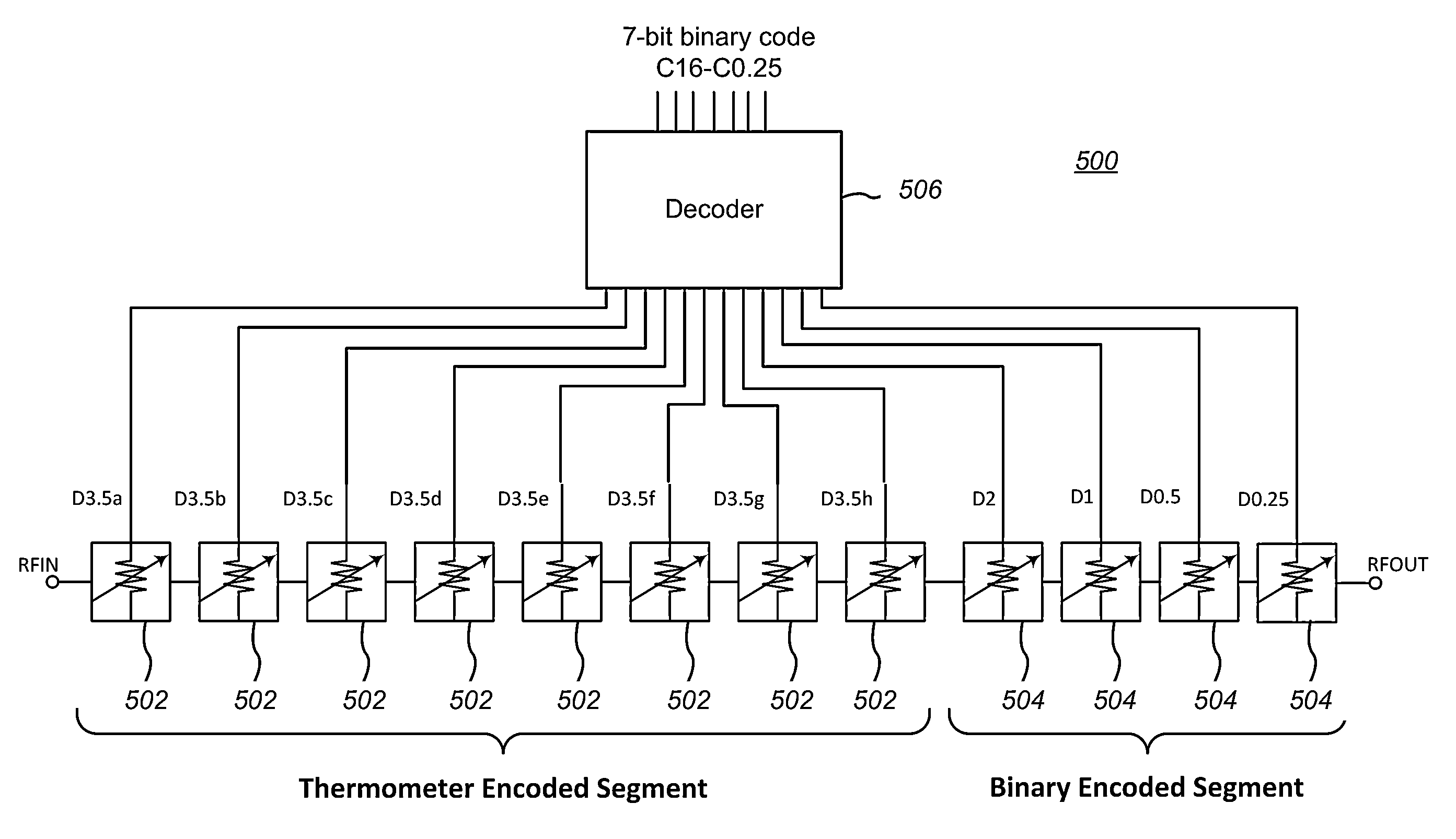
[0026]The invention is a method and circuit for significantly reducing switching transients (glitches) (both positive and negative) of digital step attenuators (DSA's) by employing a segmented DSA architecture that combines thermometer and binary coded stages. This approach reduces the number of attenuator stages switching at the same time and thus minimizes any glitch amplitude.

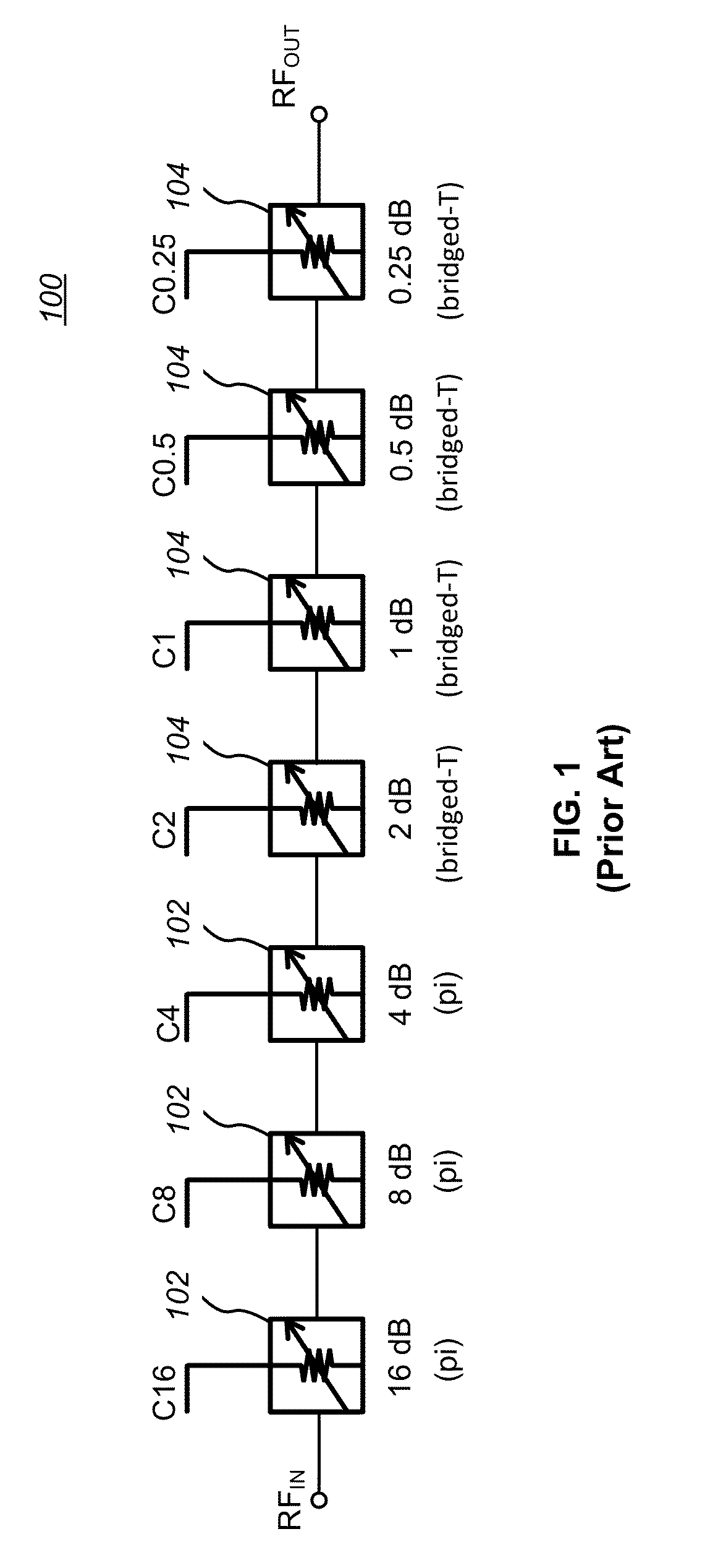
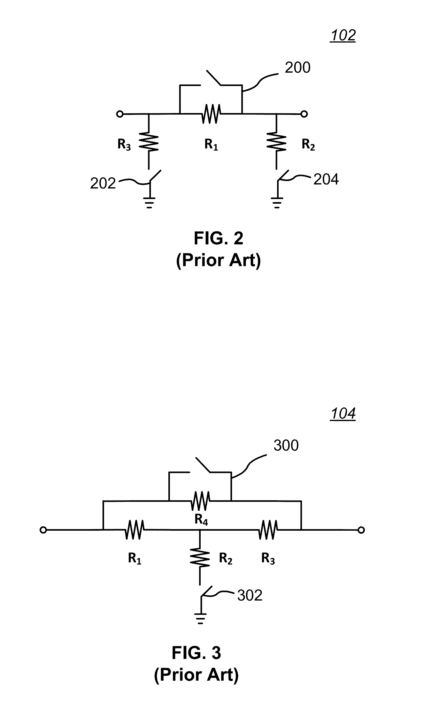
[0027]A segmented architecture reduces the number of simultaneously switched attenuators, but the total number of stages is increased. Thus, while embodiments of a segmented DSA may be realized with the same type of attenuator stages as in a purely binary-weighted DSA, the integrated circuit die (‘chip’) area may increase. Accordingly, in one embodiment, simple L-pad attenuators, each consisting of only four components, are combined in a resistor ladder network, as opposed to the series cascade of conventional attenuator stages, which typically contain six components per stage. The resistor ladder configurat...


PUM


Abstract

A method and circuit for significantly reducing the switching transients of a digital step attenuator (DSA) by employing a segmented architecture that combines thermometer and binary coded stages. This approach reduces the number of attenuator stages switching at the same time and thus minimizes any glitch amplitude. Embodiments of a segmented DSA may be realized with “pi” and “bridged-T” attenuators, as well as with simple tuned L-pad attenuators combined in a resistor ladder network.

Description

BACKGROUND[0001](1) Technical Field[0002]This invention generally relates to electronic circuits, and more specifically to digital step attenuator circuits.[0003](2) Background[0004]An attenuator is an electronic device that reduces the power of a signal without appreciably distorting its waveform. Attenuators are usually passive devices made from simple voltage divider networks, and are frequently used to lower voltage, dissipate power, and / or to improve impedance matching. For example, in measuring signals, attenuators are used to lower the amplitude of a signal under test a known amount to enable measurements, or to protect the measuring device from signal levels that might damage it. Attenuators are also used to match impedance by lowering the apparent standing wave ratio (SWR).[0005]Digital step attenuators (DSA's) are frequently used with radio frequency (RF) systems such as transceivers for broadcast radio, cellular telephones, and RF based digital networks (e.g., WiFi, Bluet...

Claims


Application Information

Patent Timeline
Patent Type & Authority Patents(United States)
IPC IPC(8): H03H11/24
CPCH03H11/245
Inventor COSTA, DAMIAN
Owner PSEMI CORP
Why Eureka
Try Eureka