Boundary layer disk turbine systems for hydrocarbon recovery

a technology of hydrocarbon recovery and boundary layer disk, which is applied in the direction of machines/engines, fluid couplings, couplings, etc., can solve the problems of significant adverse environmental and health effects, significant monetary loss of a potential revenue stream, and the pressure difference between flash gas and the sales line is too larg

Inactive Publication Date: 2016-08-09
TRI POINT OIL & GAS PRODN SYST LLC
View PDF27 Cites 1 Cited by
  • Summary
  • Abstract
  • Description
  • Claims
  • Application Information

AI Technical Summary

Benefits of technology

[0010]Provided herein are various industrial processes, and systems that incorporate those industrial processes, wherein one component of the process relates to a flow of a drive fluid that is an integral part of the industrial process. Flow of the drive fluid is used to provide power or control to other components of the process. In this manner, the flowing fluid itself can significantly reduce or avoid the requirement for an external power source to control or drive the process, including driving specific components thereof. In an aspect, the drive fluid may be the gas phase portion of a hydrocarbon recovery or storage unit, such as a vapor gas that flashes from the liquid phase. The vapor gas may be under pressure, and released to a conduit connected to a boundary layer disk turbine (BLDT), so that the pressurized vapor gas flows over the BLDT under a pressure gradient, thereby mechanically driving the BLDT. The BLDT can then be connected and employed in various configurations to advantageously drive other components depending on the specific industrial process. For example, pneumatics can be powered by connecting the BLDT to a compressor pump to compress a compressible fluid, such as air, wherein the compressed fluid is controllably used to power pneumatics as desired. Alternatively, the compressor pump may compress a hydrocarbon vapor gas to a desired pressure, such as to a desired sales or pipeline pressure. Alternatively, the BLDT can be used to both compress hydrocarbon vapor gas and to compress another fluid, such as air, to run a pneumatic device within the industrial process.
[0037]One embodiment of the present invention is directed to a self-powered compressor. “Self-powered” refers to a compressor capable of reliably running for extended periods of time without a source of electrical or chemical energy, and instead relies on fluid flow inherent in the industrial process itself to mechanically drive a compressor. In an aspect, the self-powered compressor comprises a pressure vessel containing a source of pressurized drive fluid, and a closed-loop circuit fluidically connected to a boundary layer disk turbine (BLDT) and the pressure vessel. The closed-loop circuit provides flow of the pressurized drive fluid to the BLDT under a pressure differential without loss or bleeding of the drive fluid. A compressor pump is mechanically connected to the BLDT, wherein flow of the pressurized drive fluid mechanically powers the compressor via the BLDT motion. “Pressurized fluid” refers to the fluid being at a sufficiently high pressure that it is capable of flowing over the BLDT, thereby turning the BLDT. The BLDT is, in turn, mechanically coupled directly or indirectly, to the compressor pump such that motion of the BLDT results in compressor pump compressing a compressible fluid.

Problems solved by technology

Instead of recovering this gas, it is often vented or incinerated in a combustor, leading to significant monetary loss of a potential revenue stream and significant adverse environmental and health impacts.
One reason why these hydrocarbon gases are not readily recovered is that the pressure differential between the flash gas and the sales line is too great.
Gas-powered processes, however, suffer from a number of drawbacks, including environmental and operational disadvantages.
The health effects of hydrocarbon emissions are also considered to be highly dangerous.
With respect to operational disadvantages and constraints, electric or gas-powered (natural gas or gasoline) driven compressors require components that can be very costly to purchase, operate and maintain.
Furthermore, remote drilling sites may not have electric hook-up.
Running gas-powered devices to recover hydrocarbon gas reduces the hydrocarbon end-capture, decreases economic yield and decreases capture efficiency.
Maintenance can become an issue for both electric and gas powered systems, which is further compounded by sites that are not readily accessible.
For example, all the same issues exist in a multitude of facilities including plants and offshore drilling rigs.

Method used


Image

  • Boundary layer disk turbine systems for hydrocarbon recovery
  • Boundary layer disk turbine systems for hydrocarbon recovery
  • Boundary layer disk turbine systems for hydrocarbon recovery

Examples


example 1

Disk Turbine Vapor Recovery System

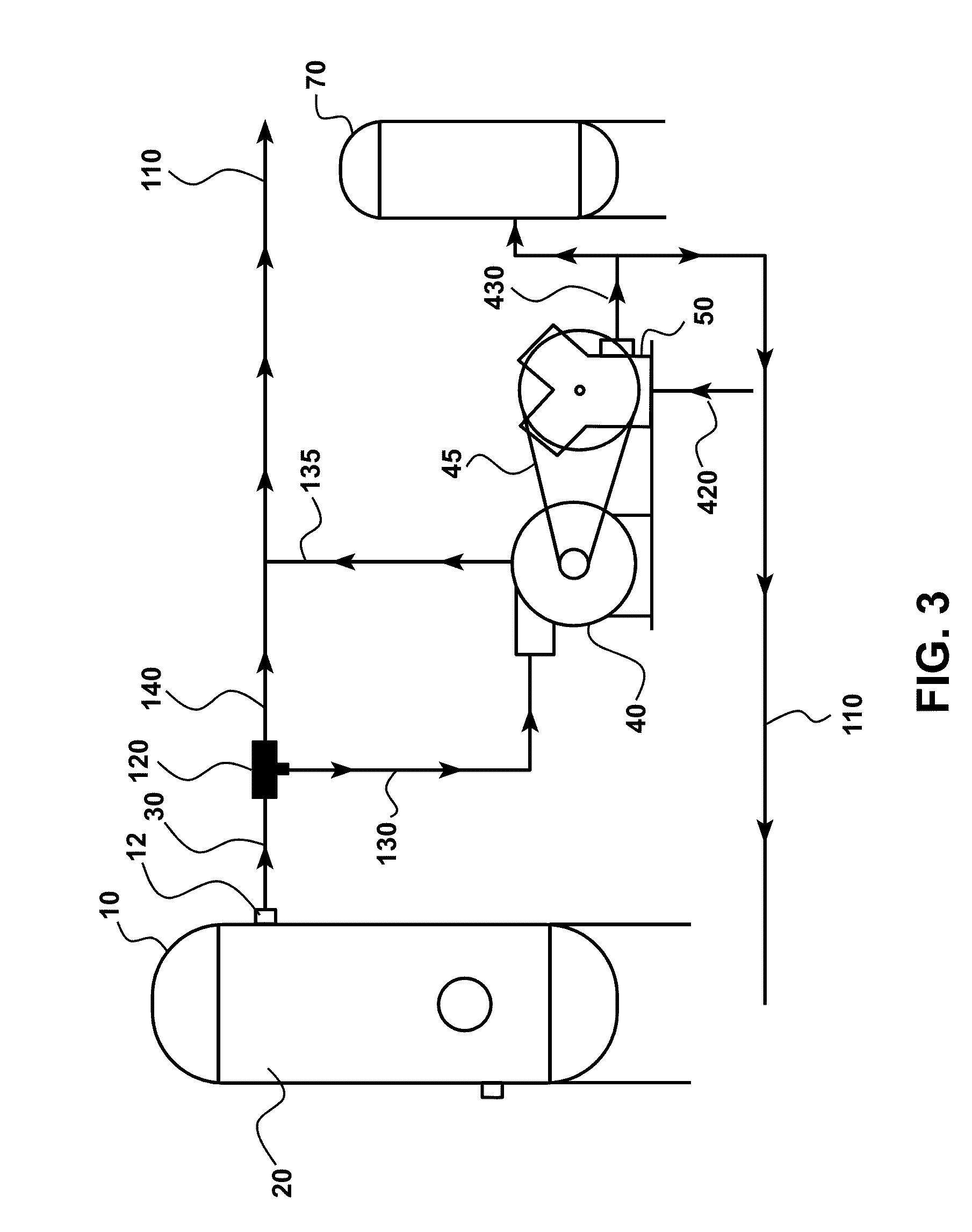
[0073]FIG. 3 summarizes a method and system for vapor recovery, such as hydrocarbon vapor recovery. Pressure vessel 10 and controller 12 provides flow of drive fluid 30, such as pressurized hydrocarbon gas, to BLDT inlet conduit 130 and to BLDT 40. BLDT 40 is mechanically connected to compressor pump 50 to compress a compressible fluid 420. The compressible fluid 420 may itself be hydrocarbon vapor, such as hydrocarbon vapor stored in a retention or separation tank (not shown). Flow of the drive fluid 30 over BLDT 40 provides motion to the disks in the BLDT and, thereby, mechanically powers compressor pump 50 by mechanical coupling 45. In this fashion, the pressurized drive fluid 30 flowing over the BLDT 40 mechanically powers compressor pump 50. In the embodiment of FIG. 3, the drive fluid is in a closed loop, such that after exiting the BLDT 40, drive fluid is provided to outlet conduit 135 and optionally to sales line 110. Alternatively, the driv...

example 2

Self-Powered Compressor

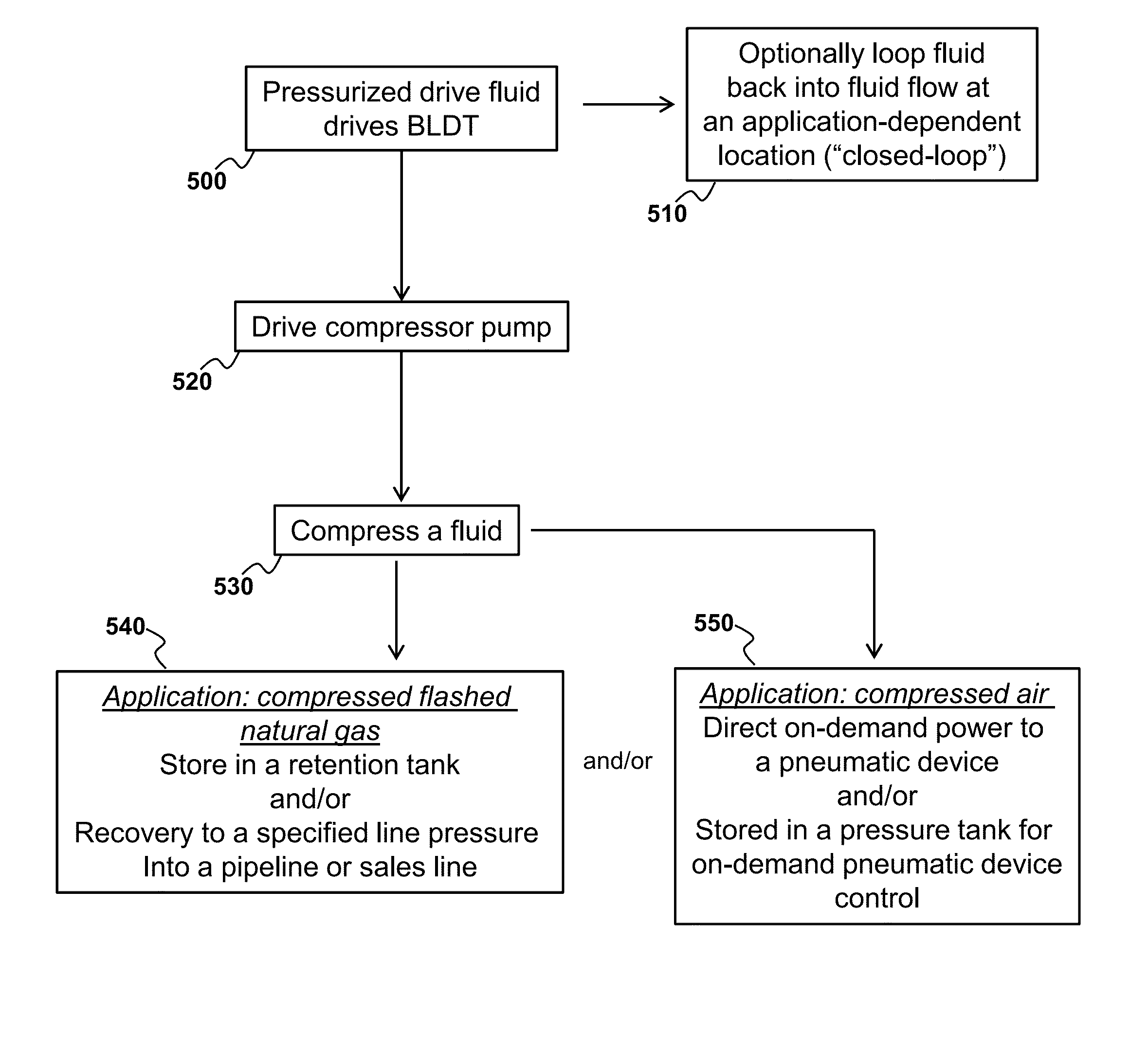
[0077]One important aspect of the industrial processes provided herein is the compressor pump that is powered by fluid flow, wherein the fluid flow is an inherent part of the industrial process and external energy input is not required to generate the flow. This aspect is referred to as a “self-powered compressor” as no external source of energy is required to drive the compressor, but the inherent high pressure of the drive fluid is harnessed to generate mechanically-based compression. As discussed, the action of the compressor can itself be harnessed to provide useful control of various aspects of the industrial process without relying on an external energy source (see, e.g., the process flow summarized FIG. 5). This can significantly reduce the cost of the process by not only minimizing external power consumption, but by avoiding additional components, increasing reliability of the process, and reducing unwanted emissions.

[0078]FIG. 4 provides an example of...


PUM


Abstract

Provided are various devices and processes that harness the inherent kinetic energy of a flowing pressurized fluid to drive a compressor to compress a fluid without any need for electrical or chemical energy. The flowing fluid flows over a boundary layer disk turbine, or Tesla turbine, which is mechanically coupled to a compressor that compresses a fluid. The flowing fluid may be a natural gas from a hydrocarbon recovery operation. The compressed fluid may be a vapor gas from a hydrocarbon production, processing, or storage facility. Harnessing the kinetic energy of the flowing fluid increases economic efficiency of the process, while also avoiding unwanted emissions adverse to the environment and public health.

Description

CROSS-REFERENCE TO RELATED APPLICATIONS[0001]This application claims the benefit of priority of U.S. Provisional Patent Application No. 61 / 535,173, filed Sep. 15, 2011, which is hereby incorporated by reference in its entirety.BACKGROUND OF THE INVENTION[0002]Provided herein are devices and methods for driving and controlling industrial processes using inherent kinetic energy of a fluid that is an integral part of the industrial process. In this manner, the environmental impact from the industrial process is significantly reduced and revenue to the producer increased, while maintaining and even increasing reliability and efficiency.[0003]Processes and systems are disclosed herein for recovering hydrocarbon vapors that are “flashed” from a liquid phase in an industrial process. These processes and systems are useful in an industrial process relating to hydrocarbon vapor recovery units (VRU) for use in a variety of hydrocarbon recovery applications. In particular, applications provide...

Claims


Application Information

Patent Timeline
Patent Type & Authority Patents(United States)
IPC IPC(8): F01D1/36F04D17/16
CPCF01D1/36F04D17/161F05D2220/62Y10T137/0396
Inventor BEELER, CASEY L.
Owner TRI POINT OIL & GAS PRODN SYST LLC
Why Eureka
Try Eureka