
LNG ship

a technology for lng ships and hulls, which is applied in the direction of vessel construction, container discharging methods, hull parts, etc., can solve the problems of high risk of sts cargo handling on the ocean, damage to the hull, and care needs to be taken, so as to reduce the risk of sloshing, the effect of reducing the volume of the tank and reducing the risk of damag

Inactive Publication Date: 2016-08-16
MORIMOTO
View PDF14 Cites 0 Cited by
  • Summary
  • Abstract
  • Description
  • Claims
  • Application Information

AI Technical Summary

Benefits of technology

The patent describes a new design for an LNG ship that reduces the risk of damage to the main tank and prevents sloshing, which can occur when the liquid level in the tank reaches the head tank. The design includes a double hull structure and longitudinal bulkheads to protect the main tank. The ship also has an independent LNG storage tank that prevents the liquid level from staying in a dangerous zone for too long. These features improve safety and efficiency of the LNG ship.

Problems solved by technology

However, since how the LNG storage tank is used is different between the LNG-FPSO and the LNG carrier, care is needed.
Considering that the cargo handling for a conventional LNG carrier has been performed while the LNG carrier is is moored at a berth provided in a safe port, it is thought that the aforesaid STS cargo handling on the ocean has a high risk, and a collision accident occurs between the LNG-FPSO and the LNG carrier trying to approach it to damage the hull, or an accident such as the damage of the hull could occur due to leakage of the liquid cargo from the loading arm.
Due to its spherical shape, the self-supporting spherical tank has a disadvantage of low volumetric efficiency because it is not well fitted in the hold.
This type requires void space between the prismatic tank and an inner hull of the ship, which accordingly reduces volumetric efficiency of the tank.
On the other hand, it has a disadvantage that the membranes and the heat insulation layer are likely to be damaged by the sloshing of a liquid cargo.
It also has a problem that a thermal insulation work, in particular, the welding of the membranes is complicated and it requires a long period for the construction.

Method used


Image

  • LNG ship
  • LNG ship
  • LNG ship

Examples


Embodiment Construction

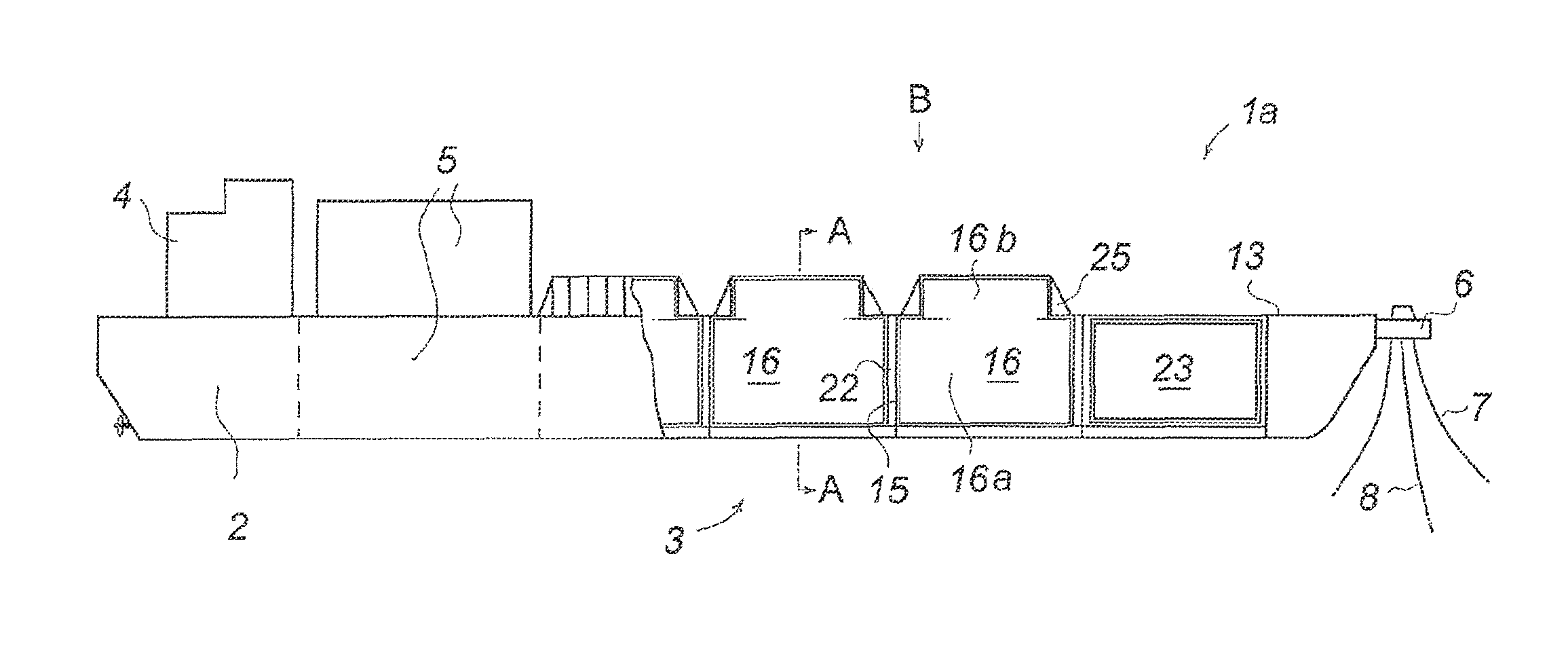
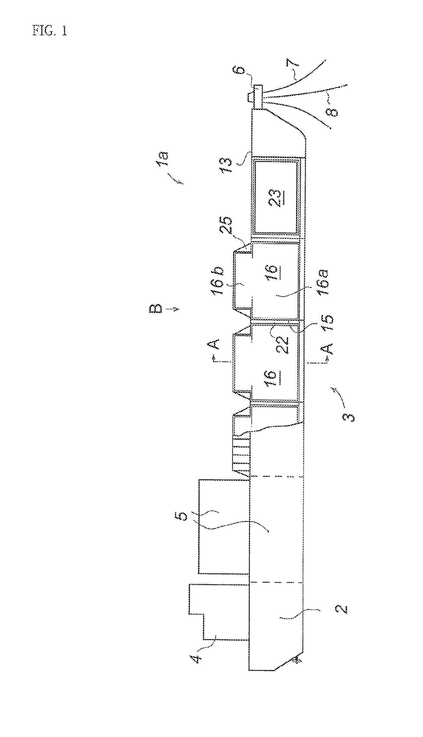
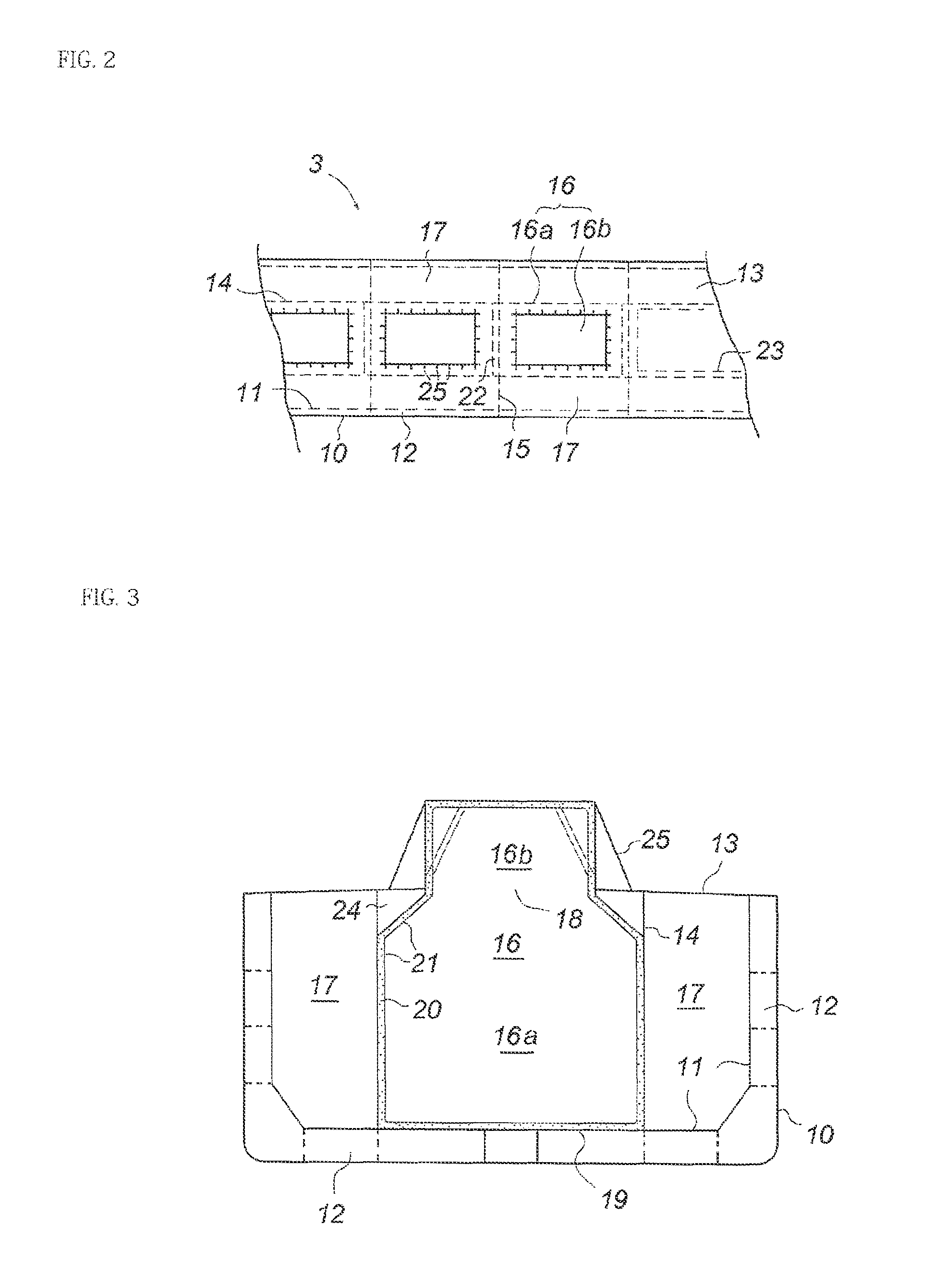
[0020]FIG. 1 is a side view of a LNG-FPSO denoted by reference sign 1a, is according to this invention. Note that this ship is remodeled from a ship which is originally a ship exclusive for crude oil / ore. Of course, it can be newly built from the first. In its stern, there is an engine room 2, and an area in front of the engine room 2 is a tank space 3. In the rear of an upper deck, there is an accommodation area 4, and in front thereof, a LNG production plant 5 is mounted. On a bow part, a turret 6 that a LNG-FPSO commonly has is provided, and a mooring wire rope 7 extending from an anchor fixed to the bottom of the sea is connected to this turret to perform various kinds of works in a single-point mooring state. A riser pipe 8 rising from the bottom of the sea is also connected to the turret, and natural gas collected from a gas field is sent through this pipe to the LNG production plant 5 on board. The natural gas is refined and liquefied here and sent to and stored in several LN...


PUM


Abstract

Provided is a LNG storage tank of a membrane type mounted on a LNG-FPSO or a LNG carrier, wherein volumetric efficiency is high and sloshing does not easily occur at the time of heavy weather. In order to solve this problem, a membrane-type tank is composed of a main tank under a deck and a box-shaped head tank on the deck. These main and head tanks communicate with each other via a hole opened in the deck to form one tank. The main tank is formed by forming a heat insulation layer on inner sides of a double bottom and left and right longitudinal bulkheads and further by liquid-tightly covering the top by a membrane of Invar or the like. Similarly, the head tank also has a heat insulation layer and a membrane provided on its inner surface.

Description

TECHNICAL FIELD[0001]The present invention relates to a LNG ship including a tank for storing LNG (liquefied natural gas). The term “LNG ship” is used as including not only a LNG carrier for carrying LNG from a place where it is produced to a place where it is consumed but also a LNG-FPSO (Floating LNG Production, Storage and Off-Loading system) in which a LNG storage tank and a LNG liquefaction plant are mounted on a barge and a LNG-FSRU (Floating LNG Storage and Re-gasification Unit) in which a LNG storage tank and a re-gasification plant are mounted on a barge.BACKGROUND ART[0002]Under circumstances where the price of energy is rising worldwide, development projects of a large-scale gas field of seabed far from land are currently beginning in earnest. A LNG-FPSO used for this has functions of liquefying gas, which is produced from a gas field of seabed, on the ocean to produce LNG, storing the LNG in a tank, and loading it onto a LNG carrier. (Note that a LNG-FSRU has a function ...

Claims


Application Information

Patent Timeline
Patent Type & Authority Patents(United States)
IPC IPC(8): B63B25/16B63B3/20F17C13/08
CPCB63B25/16B63B3/20F17C13/082B63B2241/10F17C2260/016F17C2270/0105B63B11/02B63B11/04B65D88/12B65D90/06
Inventor MORIMOTO
Owner MORIMOTO
Learn More