Magnetic resonance hyperpolarization and multiple irradiation probe head

a multi-irradiation, magnetic resonance technology, applied in the direction of magnetic measurement, magnetic variable regulation, instruments, etc., can solve the problems of sacrificing the sensitivity of rf, not suited to large planar samples, and not suited to solenoid irradiation at high power

Active Publication Date: 2016-09-20
CONSIGLIO NAT DELLE RICERCHE
View PDF3 Cites 3 Cited by
  • Summary
  • Abstract
  • Description
  • Claims
  • Application Information

AI Technical Summary

Benefits of technology

[0014]The proposed probe head, as claimed in the annexed claim 1, is aimed to solve the problem of providing devices generating and detecting RF electromagnetic radiation efficiently, being also compatible with a simultaneous, controlled, uniform, and efficient irradiation with MW electromagnetic radiation of small and large samples, also at very high MW powers, in presence of static or quasi-static magnetic and electric fields, for those cases in which the success of the application is related to a controlled amplitude and distribution of the electromagnetic, static, and quasi-static fields on the sample.
[0017]The invented structure leads to two main functionalities. The first one is to impose suitable boundary conditions on the high frequency electromagnetic waves generated by external sources, here defined as MW (down to few GHz) or higher frequency waves. In particular, the boundary conditions are designed to allow an efficient electromagnetic irradiation of the sample with a controlled electromagnetic field distribution, obtained shaping the conducting element and the grid polarizers according to the phase front of the microwave beam. The second functionality is to allow an efficient and controlled generation of low frequency electromagnetic fields in the region of the sample, here defined as RF (up to few GHz) or lower frequency signals, as well as an efficient detection of the low frequency electromagnetic fields generated by the sample.

Problems solved by technology

However, as proposed so far, the solenoid is not suited for a controlled MW irradiation of the sample at high power, due to the distortion induced on the MW field in the sample region, which can generate a relevant dielectric heating of the sample.
Moreover, it is not suited for large planar samples, which can be studied only increasing the size, thus sacrificing the RF sensitivity.
Moreover, it is not suited for a controlled MW irradiation of the sample at high power, since also in this case a strong distortion in the MW field distribution is expected around the metallic stripes edges.
The presence of a double ground plane shielding the central conductor of the stripline and the adjacent regions in which the sample can be usefully placed, make them unsuited for a simple and efficient MW irradiation of the sample at high power.
In the most sensitive versions, the RF magnetic field generated by the RF transducer is very inhomogeneous, limiting the application to extremely minute samples.
This probe head is suited for thin samples, where it shows, however, a relatively modest RF filling factor, which translates in a limited sensitivity.
For thick samples, it suffers of scarce RF field homogeneity.
This probe head is suited again for thin samples, where it shows, however, a relatively modest RF filling factor, which translates in a limited sensitivity, analogously to the previous case.
For thick samples, it suffers of scarce RF field homogeneity.
In conclusion, none of the above cited probe heads and related devices can solve the numerous issues that influence, often simultaneously, the efficiency of the hyperpolarization and multiple irradiation techniques in magnetic resonance, as the sensitivity of the measurement; the dielectric heating of the sample; the compatibility with complex microfluidic structures and with large planar samples; the homogeneity of the RF irradiation; the efficiency and the control of the MW irradiation and the susceptibility broadening.

Method used


Image

  • Magnetic resonance hyperpolarization and multiple irradiation probe head
  • Magnetic resonance hyperpolarization and multiple irradiation probe head
  • Magnetic resonance hyperpolarization and multiple irradiation probe head

Examples


Embodiment Construction

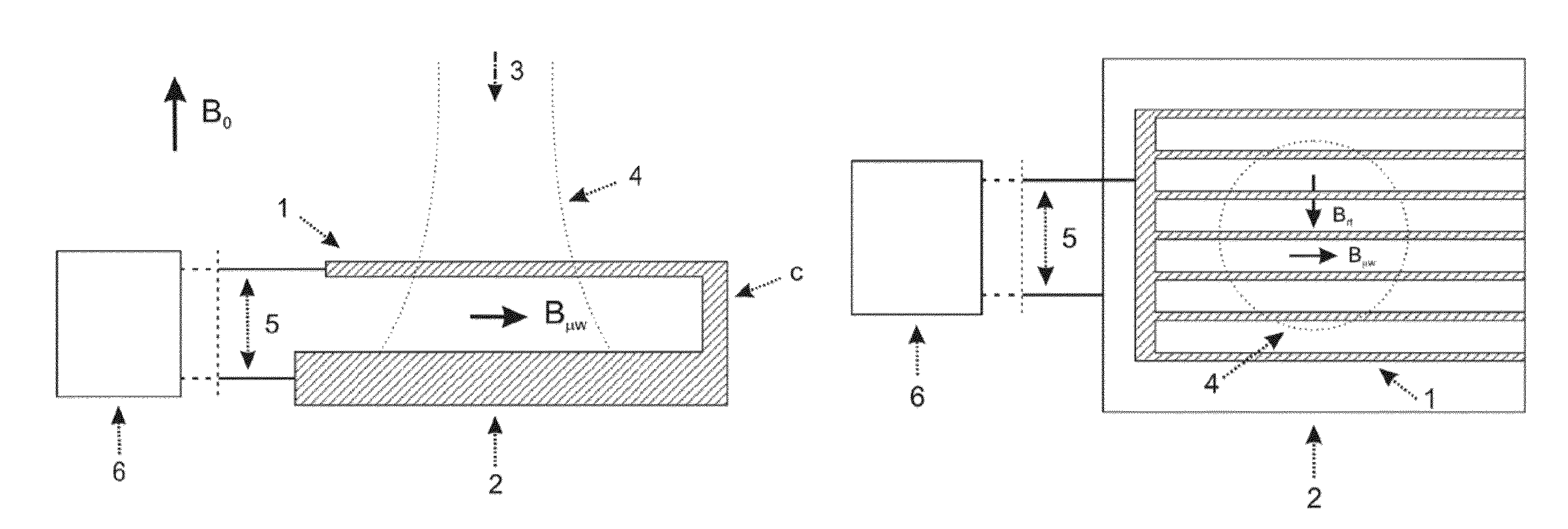
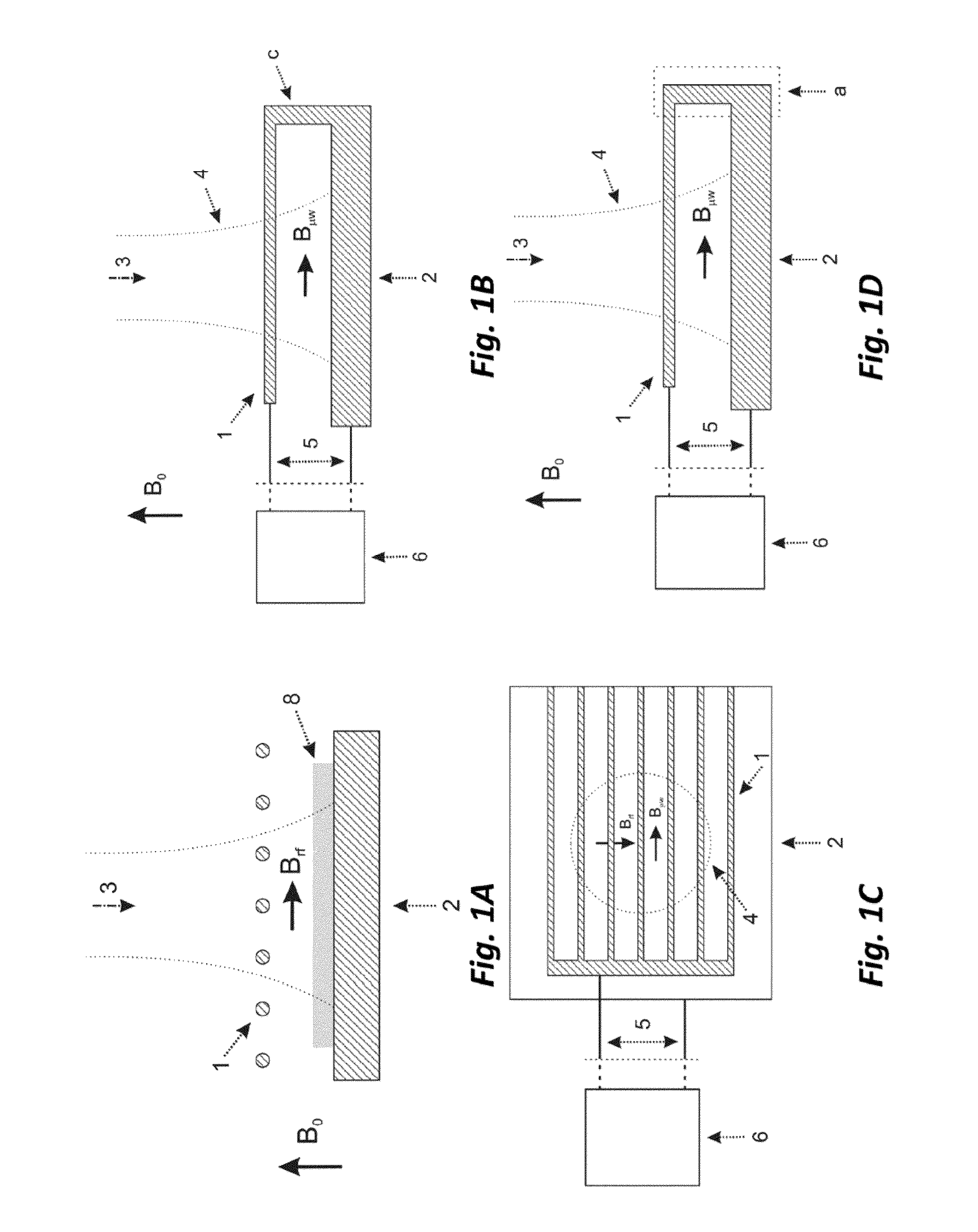
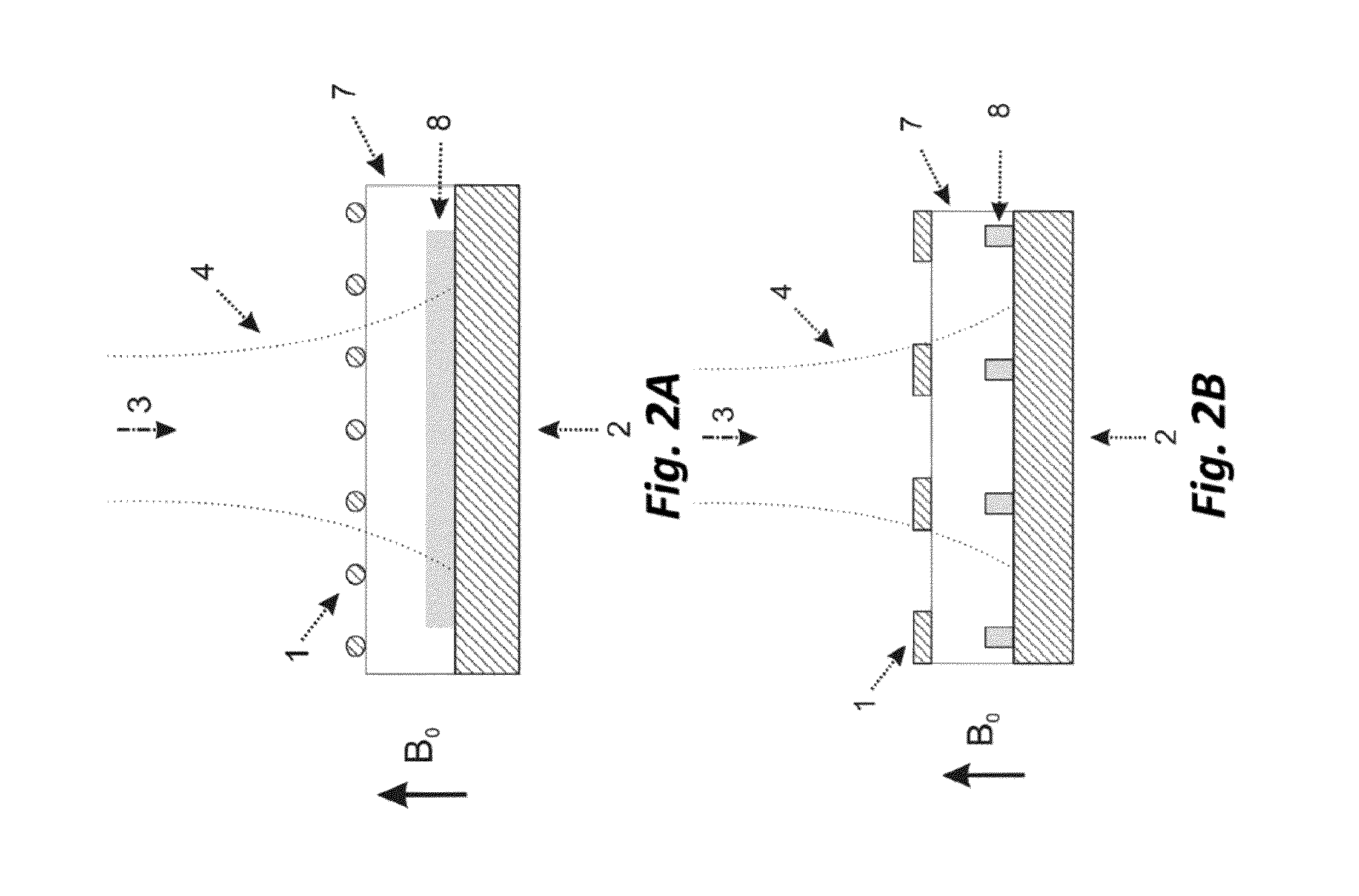
[0070]In the framework of the above mentioned magnetic resonance techniques, a sample placed in an external static magnetic field B0 is irradiated with electromagnetic waves at frequencies typical of nuclear Zeeman transitions (NMR transitions, corresponding to RF excitation with frequencies up to few GHz) or with frequencies typical of electron Zeeman transitions (EPR transitions, corresponding to MW excitation with frequencies up to few THz). These two kinds of excitation are combined in the Dynamic Nuclear Polarization-like techniques, where said MW excitation is employed with the goal of saturating the electron spin transitions of the paramagnetic species or more generally to modify the related electron spin populations and coherences. The variation of the electron states affects the nuclear spins, whose state is revealed through the NMR techniques (DNP-NMR, DNP-MRI, etc.). A proper application of this double-excitation technique can introduce an enhancement in the NMR signal of...


PUM


Abstract

A hyperpolarization and multiple irradiation probe head, suitable for use in connection with magnetic resonance techniques (DNP-NMR, photo-DNP-NMR, ENDOR-EPR, MRI, DNP-MRI), comprising a RF transducer for generating and detecting a RF signal, wherein said RF transducer has a conducting element (2) allowing, together with at least one fully or partially connected grid polarizer made of conducting grid elements (1) which are reciprocally spaced so as the grid is at least partially transparent to a given microwave beam (3), controlled RF current paths and a substantially uniform RF magnetic field inside the RF transducer, wherein the grid polarizer (1) and the conducting element (2) forming the RF transducer are shaped and oriented to conform to said microwave beam phase fronts, said grid polarizer and said conducting element surrounding a sample (8), which is apt to be irradiated also by said microwaves (3); the probe head being also suited for a simultaneous irradiation of the sample with THz, FIR, IR, visible, and UV electromagnetic radiation.

Description

BACKGROUND OF THE INVENTION[0001]1. Field of the Invention[0002]The present invention is related to a probe head for hyperpolarization and in general for multiple electromagnetic irradiation of a sample, the probe head acting as radiofrequency (RF) signal transducer, i.e. transducer intended both for generating a RF electromagnetic field suitable for the analysis of the sample by means of Nuclear Magnetic Resonance (NMR) spectroscopy, Magnetic Resonance Imaging (MRI) techniques, and Electron-Nuclear Double Resonance (ENDOR) technique in Electron Paramagnetic Resonance (EPR), the latter also known as Electron Spin Resonance (ESR), as well as for detecting a RF field signal generated by the sample in a way suitable for NMR and MRI techniques, the probe head also allowing a simultaneous, controlled, and efficient irradiation of the sample by microwaves (MW or μN) and higher frequency waves.[0003]With the term hyperpolarization it is intended a kind of nuclear spin polarization of a mat...

Claims


Application Information

Patent Timeline
Patent Type & Authority Patents(United States)
IPC IPC(8): G01R33/28G01R33/345G01R33/62G01R33/20G01R33/30
CPCG01R33/282G01R33/20G01R33/3456G01R33/62G01R33/302
Inventor ANNINO, GIUSEPPEMACOR, ALESSANDRODE RIJK, EMILEALBERTI, STEFANO
Owner CONSIGLIO NAT DELLE RICERCHE
Why Eureka
Try Eureka