WDM Mux/DeMux on cable and methods of making the same

a technology of wdm mux/demux and cable, applied in the field of optical communication, can solve the problems of high power coupling loss, laser input will have to suffer at least 75% (or 6 db) minimum power loss, and no compact and right power consumed electro-optic modulator can handle such a high bandwidth data single handedly, so as to reduce the pressure on tosa/rosa and transceiver manufacturers.

Active Publication Date: 2016-11-01
ALLIAN FIBER OPTIC PROD INC
View PDF13 Cites 34 Cited by
  • Summary
  • Abstract
  • Description
  • Claims
  • Application Information

AI Technical Summary

Benefits of technology

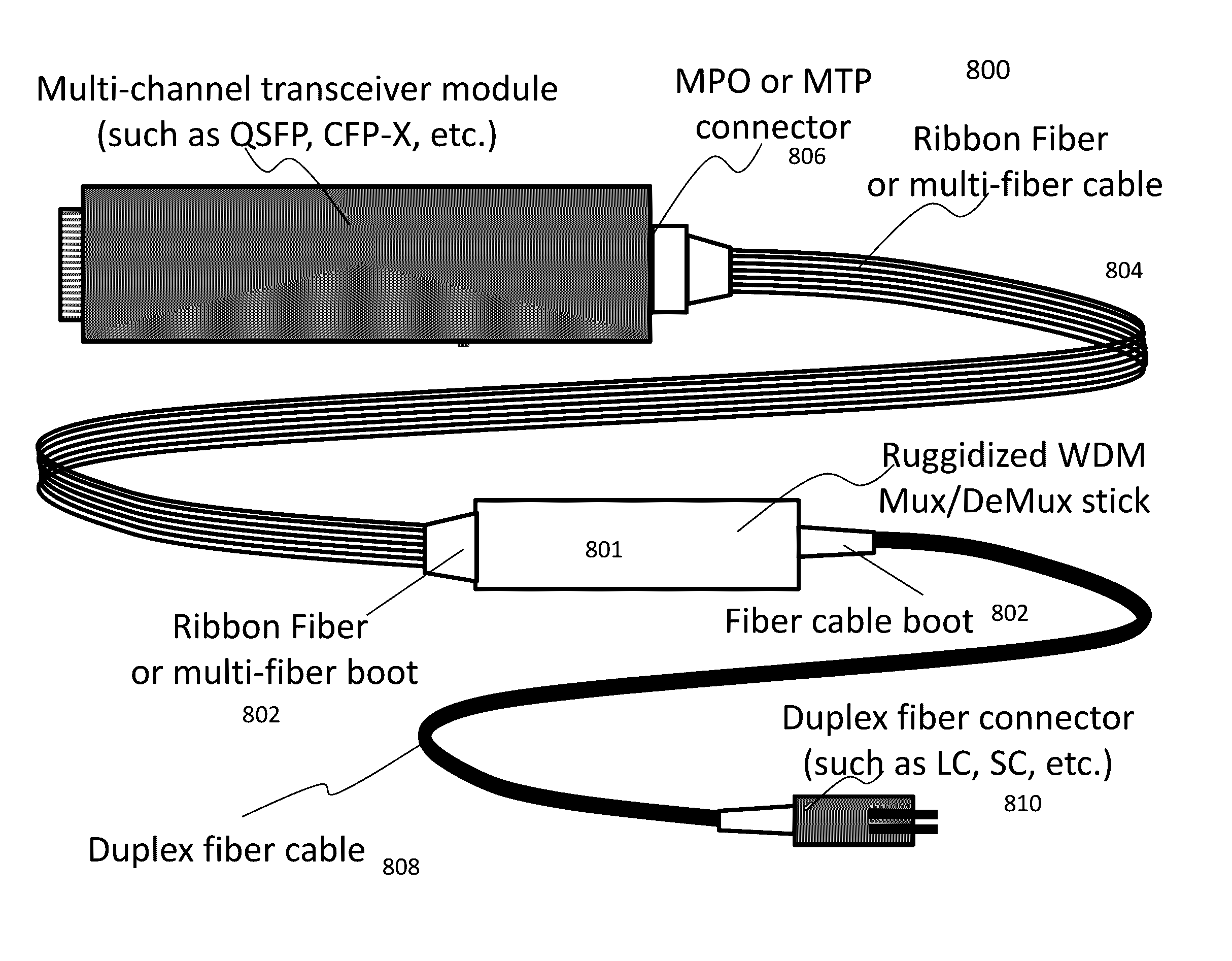
[0019]One of the advantages, objects and benefits in the present invention is to alleviate the pressure on the TOSA / ROSA and transceiver manufacturers to provide more spaces with passive optical functions such as Mux / DeMux. This is done by separating out those functions out of a multi-wavelength transceiver to a unit on cable.

Problems solved by technology

Fibers that facilitate much of such land-line bandwidth supports in the past now challenge device and equipment development to keep up the speed to fill their available bandwidth capacities.
This is largely because even by using various data compression and forward error correction (FEC) techniques, no compact and right power consumed electro-optic modulator can handle such a high bandwidth data single handedly.
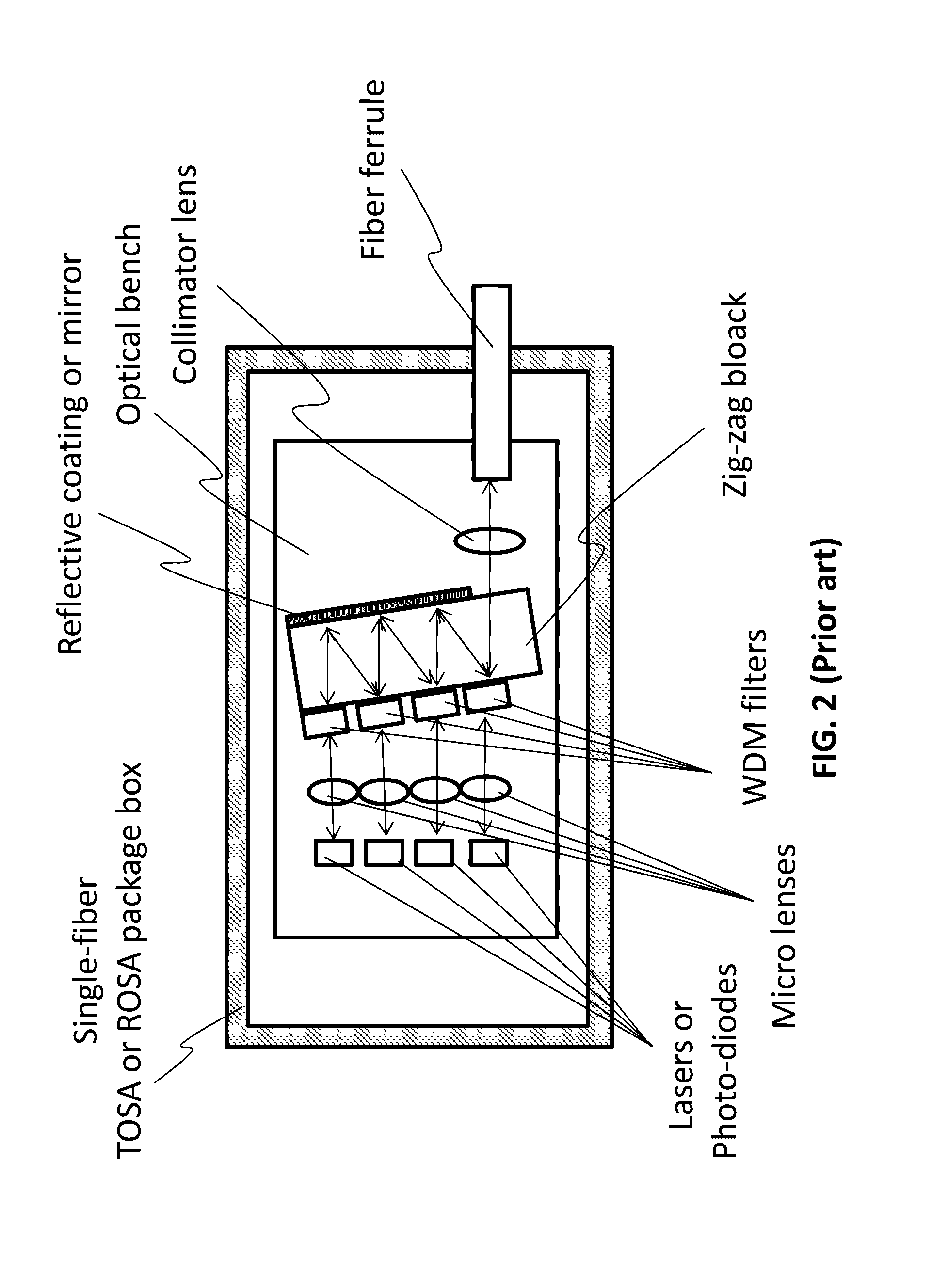
There are no filters or mirrors employed but the price to pay for the simplicity is that any of the laser input will have to suffer at least 75% (or 6 dB) minimum power loss due to basic physics constraints of combing SM optical power using a splitter / combiner or non-multiplexing scheme.
However, the limitation is the high power coupling loss, not only just for the >6 dB fundamental combing loss in the PLC combiner case, but also for the WDM Mux / DeMux scheme that also suffers severe waveguide bending loss associated with the high refractive index material for PLC waveguides.
However, such a chip will inevitably have much larger chip area unless a chip designer plans to endure severe bending loss (e.g., >5 dB if making the chip as compact as its silicon counterparts).

Method used


Image

  • WDM Mux/DeMux on cable and methods of making the same
  • WDM Mux/DeMux on cable and methods of making the same
  • WDM Mux/DeMux on cable and methods of making the same

Examples


Embodiment Construction

[0039]In the following description, numerous specific details are set forth in order to provide a thorough understanding of the present invention. However, it will become obvious to those skilled in the art that the present invention may be practiced without these specific details. The description and representation herein are the common means used by those experienced or skilled in the art to most effectively convey the substance of their work to others skilled in the art. In other instances, well-known methods, procedures, components, and circuitry have not been described in detail to avoid unnecessarily obscuring aspects of the present invention.

[0040]Reference herein to “one embodiment” or “an embodiment” means that a particular feature, structure, or characteristic described in connection with the embodiment can be included in at least one embodiment of the invention. The appearances of the phrase “in one embodiment” in various places in the specification are not necessarily al...


PUM


Abstract

Techniques for WDM Mux / DeMux on cable and methods of making the same are described According to one aspect of the present invention, a unit designed to provide multiplexing or demultiplexing (Mux / Demux) functions is implemented on cable. In other words, the Mux / Demux unit is coupled by a multi-fiber cable to a system (e.g., a system rack for router or switch that has multiple pluggable transceiver slots).

Description

CROSS-REFERENCE TO RELATED APPLICATION[0001]This application claims the benefits of U. S. Provisional Application No. 61 / 851,114, filed Mar. 4 / 2013, and entitled “WDM Mux DeMux on Cable and Methods of Making”, which is hereby incorporated by reference for all purposes.BACKGROUND OF THE INVENTION[0002]1. Field of the Invention[0003]The invention is generally related to the area of optical communications. In particular, the invention is related to WDM Mux / DeMux on cable and methods of making the same.[0004]2. The Background of Related Art[0005]Broadband internet has experienced a compounded annual bandwidth growth rate exceeding 30% over the last decade. The momentum shows no sign of slowing down as wireless broadband, due to the smart phones and portable devices, joins the game. Fibers that facilitate much of such land-line bandwidth supports in the past now challenge device and equipment development to keep up the speed to fill their available bandwidth capacities. In core networks,...

Claims


Application Information

Patent Timeline
Patent Type & Authority Patents(United States)
IPC IPC(8): H04B10/00G02B6/293G02B6/36
CPCG02B6/29365G02B6/3664G02B6/2938G02B6/4292G02B6/4446G02B6/4452
Inventor LI, YAOXIAO, CHARLIE
Owner ALLIAN FIBER OPTIC PROD INC
Why Eureka
Try Eureka