
Method for producing substrates for superconducting layers

a superconducting layer and substrate technology, applied in the direction of permanent superconductor devices, superconductor devices, metallic pattern materials, etc., can solve the problems of high losses when used in alternating current (ac) applications, inability to adapt the means of reducing ac losses that are currently available to continuous processing of long lengths of superconducting tape, and inability to achieve high thermal conductivity, low conductivity, and high electrical conductivity.

Active Publication Date: 2016-11-15
DANMARKS TEKNISKE UNIV
View PDF12 Cites 0 Cited by
  • Summary
  • Abstract
  • Description
  • Claims
  • Application Information

AI Technical Summary

Benefits of technology

[0008]In particular, it may be seen as an object of the present invention to provide a method of making a substrate for a superconducting tape having reduced AC losses which is adaptable to continuous processing of long lengths of such tape and which method is effective, cheap and / or which provides an improved substrate for a superconducting tape that solves the above mentioned problems of the prior art.
[0082]According to a second aspect of the invention, there is provided a substrate suitable for supporting an elongated superconducting element, such as a superconducting tape having reduced AC losses, the substrate comprising:

Problems solved by technology

However, although they possess excellent properties when carrying direct current, they may exhibit high losses when used in alternating current (AC) applications.
Means of reducing AC losses that are currently available may not in a straightforward manner be adapted to processing long lengths of superconducting tape.
It may be seen as a problem with the prior art methods that they are not adaptable to continuous processing of long lengths of such tape, effective, cheap, enabling low material consumption and / or provides a good substrate for a superconducting tape.

Method used


Image

  • Method for producing substrates for superconducting layers
  • Method for producing substrates for superconducting layers
  • Method for producing substrates for superconducting layers

Examples


example a

‘Coating-cut-etched’-tapes

A1. Providing the Upper Layer: Surface Layer / coating

[0149]The starting materials were commercially available Hastelloy C276 tapes, supplied annealed, and with a bright surface finish, from Stahlwerk Ergste Westig GmbH. The Hastealloy tape may be considered a primary solid element. Samples with typical dimensions; length ˜100 mm, width ˜10 mm and thickness ˜0.1 mm, were cleaned in an ultrasonic bath using a mixture (10:1) of acetone and ethanol for 25 min, then dipped in ethanol, dried with compressed air. The samples were subsequently heat treated at 800-1000° C. for 3 h in an open tube furnace equipped with a fan in order to supply sufficient amounts of new air while growing a surface layer / coating (oxide / nitride). The surface layer may be considered the upper layer. A quartz-based holder enabled an upright positioning of the sample so that none of the tape sides, i.e., the two sides being parallel with a plane of the tape, were in contact with the sample ...

example b

‘Coating-roll-etched’-tapes

B1. Surface Layer / coating

[0167]See section A1.

B2. Rolling / disruptive Lines

[0168]A special set of profile-rolls were applied when producing disruptive lines in this method and a schematic drawing of the rolls is shown in FIG. 15.

[0169]FIG. 15 is a schematic drawing showing an upper roll 1516, being an upper profiled roller and a lower roller 1518. The height difference 1519 between the inner part of the curved part of the upper profiled roller and the edge of the curved part roll is 10 μm. Note that the drawing is not correctly scaled.

[0170]The coated tape was rolled manually without lubrication and at a low rolling speed as the rolls where driven using a set of Clyburn spanners (Swedish form). The PPR (per pass reduction) was approximately 1-20 micrometers. The speed of rolling was approximately 10 mm per second. Bright lines (indicating exposed areas) were apparent at the positions where the edge of the profiled roll had deformed the tape, and visible dur...

example c

Roll-coating-cut / cut-roll-1

C1. Profile Rolling

[0176]The sample is rolled prior to coating using a profile roll similar to that shown in FIG. 15 (with / without the “cutting-edge” with depth 1519, such as 10 micrometer, of the roll).

C2. Forming the Upper Layer: Surface Layer / coating

[0177]A surface coating is prepared (see section A1 or using e.g. Kapton® film) after the initial (C1) rolling. This surface layer is covering the entire sample surface.

C3. Forming Disruptive Strips: Cutting / cut-rolling / grinding

[0178]A subsequent cutting or cut-rolling (roll with a sharp cutting-profile, see FIG. 15) is performed in the bottom of the profile, i.e. either removing only a small part of the horizontal part of the surface coating (i.e., the upper layer), in the bottom of the profile or the entire surface coating (i.e., the upper layer), in the bottom of the profile as shown in FIG. 18.

[0179]FIG. 18 shows a schematic drawing of the method described in Example C (‘Roll-coat-cut’ method). Subfigure...


PUM

PropertyMeasurementUnit
temperatureaaaaaaaaaa

Abstract

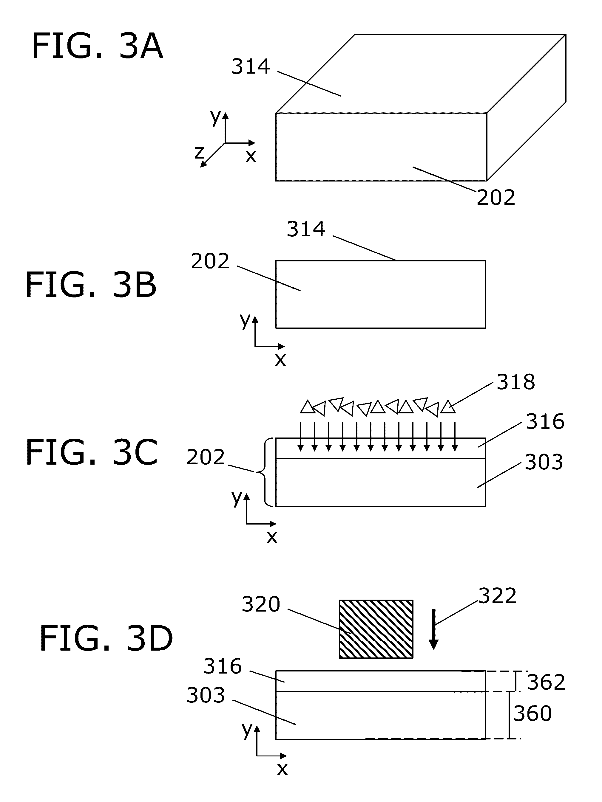
There is provided a method for producing a substrate (600) suitable for supporting an elongated superconducting element, wherein, e.g., a deformation process is utilized in order to form disruptive strips in a layered solid element, and where etching is used to form undercut volumes (330, 332) between an upper layer (316) and a lower layer (303) of the layered solid element. Such relatively simple steps enable providing a substrate which may be turned into a superconducting structure, such as a superconducting tape, having reduced AC losses, since the undercut volumes (330, 332) may be useful for separating layers of material. In a further embodiment, there is placed a superconducting layer on top of the upper layer (316) and / or lower layer (303), so as to provide a superconducting structure with reduced AC losses.

Description

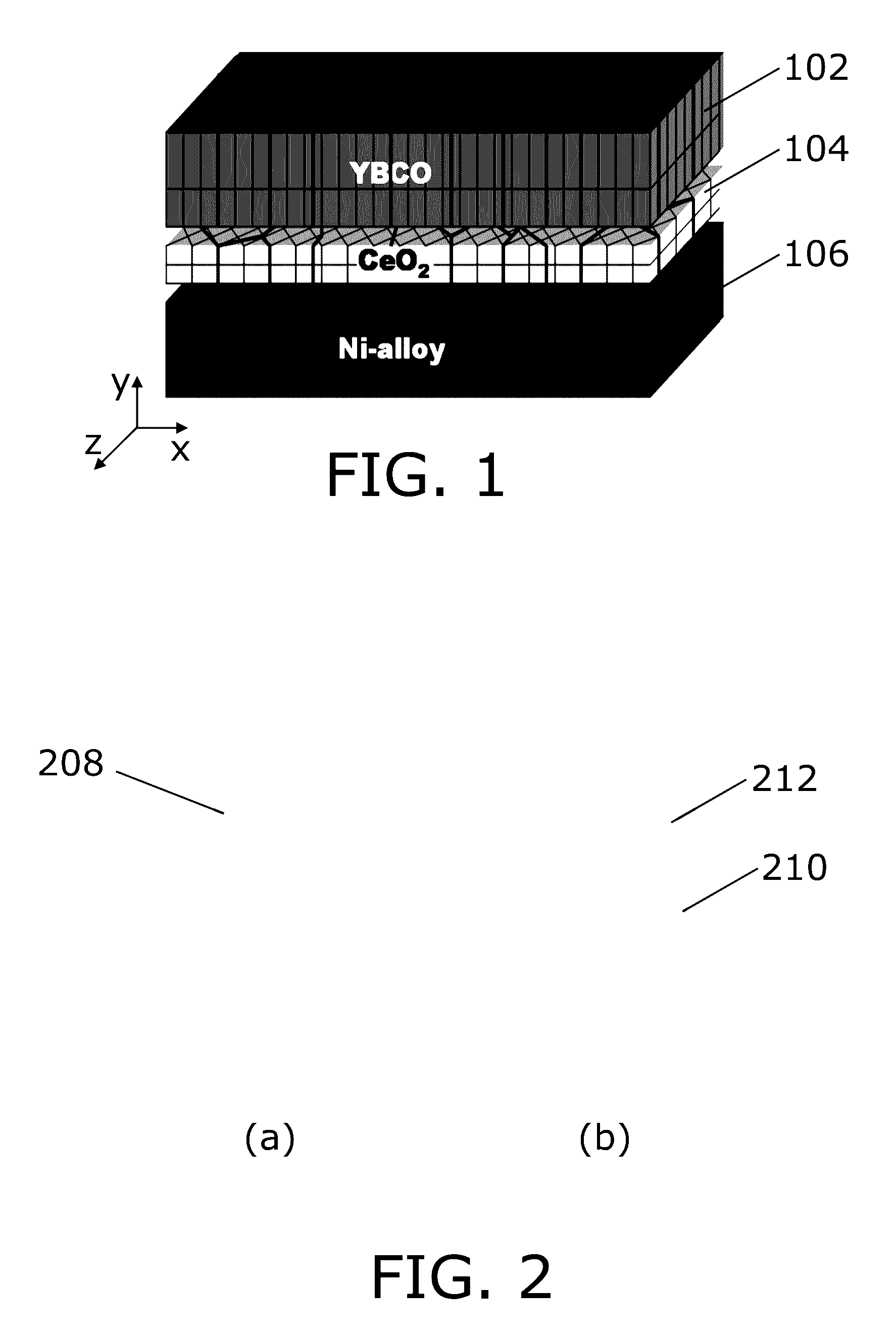
FIELD OF THE INVENTION[0001]The present invention relates to a method for producing substrates, and in particular relates to substrates suitable for supporting an elongated superconducting element, and a corresponding method for producing and using such substrates.BACKGROUND OF THE INVENTION[0002]Superconducting structures may be seen as advantageous since they enable conducting current without resistive losses. Superconducting structures, such as superconducting tapes are thus being used for a number of applications, such as generators and transformers. However, although they possess excellent properties when carrying direct current, they may exhibit high losses when used in alternating current (AC) applications.[0003]Means of reducing AC losses that are currently available may not in a straightforward manner be adapted to processing long lengths of superconducting tape.[0004]In the application U.S. Pat. No. 7,593,758 B2 there is presented a tape which has a high temperature superc...

Claims


Application Information

Patent Timeline
Patent Type & Authority Patents(United States)
IPC IPC(8): H01L39/14H01L39/24H05K1/09
CPCH01L39/2454H01L39/143H01L39/248H05K1/092Y10T29/49014H10N60/203H10N60/0576H10N60/0801H10N60/85H10N60/01
Inventor WULFF, ANDERS CHRISTIAN
Owner DANMARKS TEKNISKE UNIV
Learn More