Method and apparatus for managing process control configuration

a technology of process control and configuration, applied in the field of process plants, can solve the problems of reducing the original productivity gain obtained by using configuration class objects, time-consuming and maybe fraught with errors, and inability to change all instances associated with a particular module class object at the same time, so as to achieve the effect of easy determination and easy determination

Active Publication Date: 2016-11-22
FISHER-ROSEMOUNT SYST INC
View PDF67 Cites 10 Cited by
  • Summary
  • Abstract
  • Description
  • Claims
  • Application Information

AI Technical Summary

Benefits of technology

[0021]A configuration system uses flexible or modifiable object (e.g., module class objects, module instance objects and children objects) techniques to enable class-based configuration to be more useful and beneficial both in developing new control strategies or display elements and in making changes to these elements when these elements are being run or executed in a plant environment. Such a configuration system is interchangeably referred to herein as a “flexible configuration system,” or “configuration system.” In particular, the use of the new flexible objects reduces the proliferation of class objects and makes a single class object applicable to a wider variety of applications (uses) by allowing more variation amongst the instances made from the class object. The configuration system with the new flexible objects allows a user to, for example, add items to a classed based instance (or other child object) as required for a particular need, but in a manner that does not force the instance or child object to be removed from or disassociated from the class and in a manner that will not affect other instances of the same class unless the user wishes to push that change to the other instances or to the parent object itself. Likewise, items that are added to an instance or child object may be flagged within the instance or child object, and may be labeled so as not to interfere with anything added at the parent level and for clear documentation purposes. Still further, the configuration system with the new flexible objects supports disabling of parent content at the child level and / or deletion of parent content at the child level. Disabling or deleting the parent content at the child level allows, for example, a user to better handle the instances that need to have less functionality than the rest of the class instances, while still having the core class functionality to remain part of the class. If desired, any disabled content at the child level can be visually muted or made invisible within the configuration utilities that enable viewing of the child, and can be re-enabled by the user at any time. The disabled content will not be used in runtime, but will only reside in the configuration environment. If the user decides to include a previously disabled portion of the parent object within a child object, then that child object can be flagged for download to update the runtime version in the control system.
[0022]Moreover, the configuration system using flexible objects makes classes more usable in running plants by allowing changes or updates to be distributed to the instances and children objects in a phased manner. For example, a user or configuration engineer may selectively propagate class changes down to the instances by allowing the user to make changes to a class object and deciding which of the instances of that class object should receive those changes and at what time, which leads to increased plant performance and better runtime support, instead of forcing all class changes to be propagated to all instances of the class at once. This phasing feature allows the user to make a class change and only propagate that change to the instances that require the change. The user can then later go back and propagate the change out to more or to the rest of the instances. More particularly, this phasing feature allows the user to decide which instances can have the configuration update downloaded thereto based on current plant operational considerations and can phase in a class change over a fluid time line that makes sense within the process operation, instead of having to manage downloads manually or perform an automatic download to all instances all at once.
[0023]As another feature, the configuration system using flexible objects improves the ability of a user to incrementally make and verify changes by selective propagation of instance changes back up to the class object. For example, the configuration system enables a user to take a change that was made on an instance and to propagate this change back up to the class object for distribution back down to the rest of the instances. This feature provides the user with a built in testing environment, in which the user is able to change and test one instance before rolling that change out to all other instances of the class object.

Problems solved by technology

This process is tedious, time consuming and maybe fraught with error.
Unfortunately, as more and more of these module class objects are defined, the original productivity gains obtained by using configuration class objects decrease.
Although this automatic change propagation feature makes control system design easier and more effective in the early stages of the design, once the control system is installed and running in a plant, it may not be acceptable or practical to change all of the instances associated with a particular module class object at the same time.
However, as a practical matter, each affected child object running in the plant may need to be individually tested and verified on actual process equipment, and thus the user may need to delay the change to the module class object for months or years waiting for an appropriate time to update all of the module instances for that class object.
Many process industries cannot deal with the resulting disruptive downloads required, spanning multiple areas of the plant, during the plant operations phase.
However, this operation destroys the advantages of using class based configuration objects in the first place.
Even in smaller systems in which class / instance connections are not being severed, it is still difficult to define and debug a new change to a control object without affecting all of the instances in the class because, on the one hand, it is not possible to implement new changes on an instance, and because, on the other hand, when any change is made to the class object, this change is automatically applied to each instance of the class object.
Still further, most configuration systems used in the market today do not use classes to configure graphic displays for the control system.
As modifications to control strategies occur and the control strategy classes proliferate in the manners noted above, each graphics item for each instance needs to be verified, which becomes time consuming and impractical.
Moreover, designing instance differences in graphics is difficult and requires programming skills.
Without this up front design, the graphic objects cannot even have small changes made thereto.
Unfortunately, a configuration system which attempts to design or pre-specify the allowable changes in the graphics items quickly becomes unusable, as variations on graphics items is very common.
As a result, maintaining graphics cost effectively is an ongoing problem within control systems, and is only exacerbated when the step of maintaining graphics must be coordinated with the changes being made to control module classes used in the control configuration system.
However, there is no hard link back to the original dynamo.
There are several problems and limitations to this approach.
However, because there is no hard link between the original dynamo being changed and its copies, determining where the dynamo is used is a serious issue.
However, not all customers use this technique and, in any event, this field can be inadvertently cleared or deleted by a user during an edit session, thereby losing the named connection back to the original dynamo.
Further, if a difference was a change on the display or to the dynamo, it is only possible to know what is different in the dynamo, but not why.
Thus, it is difficult for users to determine if a change needs to be incorporated into a particular dynamo being used in a particular display when changes are made to the original dynamo.
Still further, while the user can update the instance to the new dynamo and retain the instance specific changes, the user typically does not know which changes are in the new master and which are instance specific, and so cannot determine which differences within the display item should be left in place.
As a result, the user must then manually reapply all changes previously made to the display item or instance, and if the user forgets some of the changes, these changes are lost.
This operation negatively affects the quality of the operator displays and also takes longer because it entails a manual process.
As a result, a dynamo can only be built from the basic shapes and not from other dynamos, which prevents building up a set of dynamos to be used as the basis for other dynamos.

Method used


Image

  • Method and apparatus for managing process control configuration
  • Method and apparatus for managing process control configuration
  • Method and apparatus for managing process control configuration

Examples


Embodiment Construction

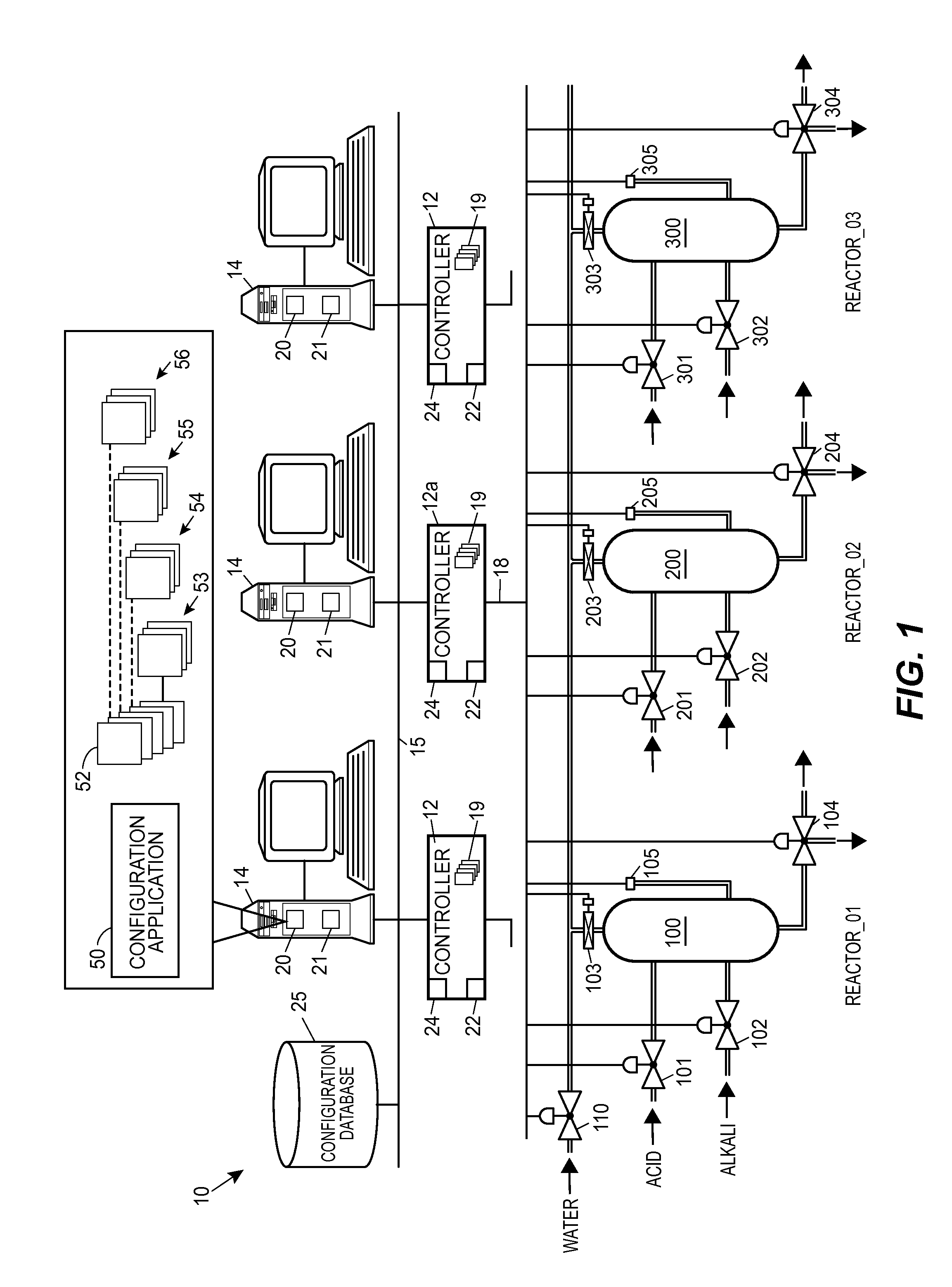
[0054]Referring now to FIG. 1, a process plant 10 includes one or more process controllers 12 coupled to numerous workstations 14 via, for example, an Ethernet connection or bus 15. The controllers 12 are also coupled to devices or equipment within the process plant 10 via sets of communication lines or buses 18, with only the set of communication lines 18 connected to the controller 12a being illustrated in FIG. 1. The communication lines or buses 18 may be, for example, wired connections, wireless connections, or a combination of wired and wireless connections. The controllers 12, which may be implemented by way of example only using the DeltaV™ controller sold by Fisher-Rosemount Systems, Inc., are capable of communicating with control elements, such as field devices and function blocks within field devices distributed throughout the process plant 10 to perform one or more process control routines 19 to thereby implement desired control of the process plant 10 or of one or more p...


PUM


Abstract

Flexible configuration of process control systems or plants allows draft changes or modifications to be made to parent process objects, e.g., in a configuration environment, without automatically triggering corresponding instantiations and / or downloads of the parent process objects and / or their derived children objects into a run-time system. Parent objects to which draft changes are allowed may include class objects, instance objects, and / or library objects. One or more modifications to a process object may be saved as a draft, and multiple drafts for a same process object may be saved as different versions. Children objects may indicate the particular version of a parent object draft from which they are derived. A user may indicate that a particular draft or version is to be published or approved. Unpublished or unapproved drafts are prevented from being instantiated in the run-time system, whereas published or approved drafts are allowed to be instantiated.

Description

CROSS-REFERENCE TO RELATED APPLICATIONS[0001]This application claims the benefit of U.S. Provisional Application No. 61 / 711,110 entitled “Process Plant Configurations Using Flexible Objects” and filed on Oct. 8, 2012, the entire contents of which are hereby incorporated by reference herein. Additionally, this application claims the benefit of U.S. Provisional Application No. 61 / 711,105 entitled “Configurable User Displays in a Process Control System” and filed on Oct. 8, 2012, the entire contents of which are hereby incorporated by reference herein.[0002]Further, this application is related to U.S. application Ser. No. 14 / 048,533, originally entitled “Dynamically Reusable Classes” and filed concurrently herewith, the entire contents of which are hereby incorporated by reference herein. This application is also related to U.S. application Ser. No. 14 / 048,516, originally entitled “Derived and Linked Definitions with Override” and filed concurrently herewith, the entire contents of whi...

Claims


Application Information

Patent Timeline
Patent Type & Authority Patents(United States)
IPC IPC(8): G05B11/01G06F3/0484G05B15/02G05B19/418
CPCG06F3/0484G05B15/02G05B19/4188G05B2219/25067G05B2219/31418G05B2219/31467G05B2219/31472G05B2219/32128Y02P90/16Y02P90/24G05B19/41845G05B19/4186G05B19/0428G05B2219/24215G05B2219/33273Y02P90/02G05B19/042G05B19/418G06F9/44G05B23/02
Inventor JUNDT, LARRY O.LUCAS, J. MICHAELLEWIS, MARTY JAMES
Owner FISHER-ROSEMOUNT SYST INC
Why Eureka
Try Eureka