Link actuation device
a technology of actuation device and link, which is applied in the direction of programmed manipulators, instruments, and manipulators. it can solve the problems of difficult to operate the link actuation device viscerally, and increasing the size of the bearing mounting portion and/or the gear mounting portion. it can improve the driving balance of each of the actuators, shorten the stabilization time of the distal end side link hub, and improve the effect o
- Summary
- Abstract
- Description
- Claims
- Application Information
AI Technical Summary
Benefits of technology
Problems solved by technology
Method used
Image
Examples
second embodiment
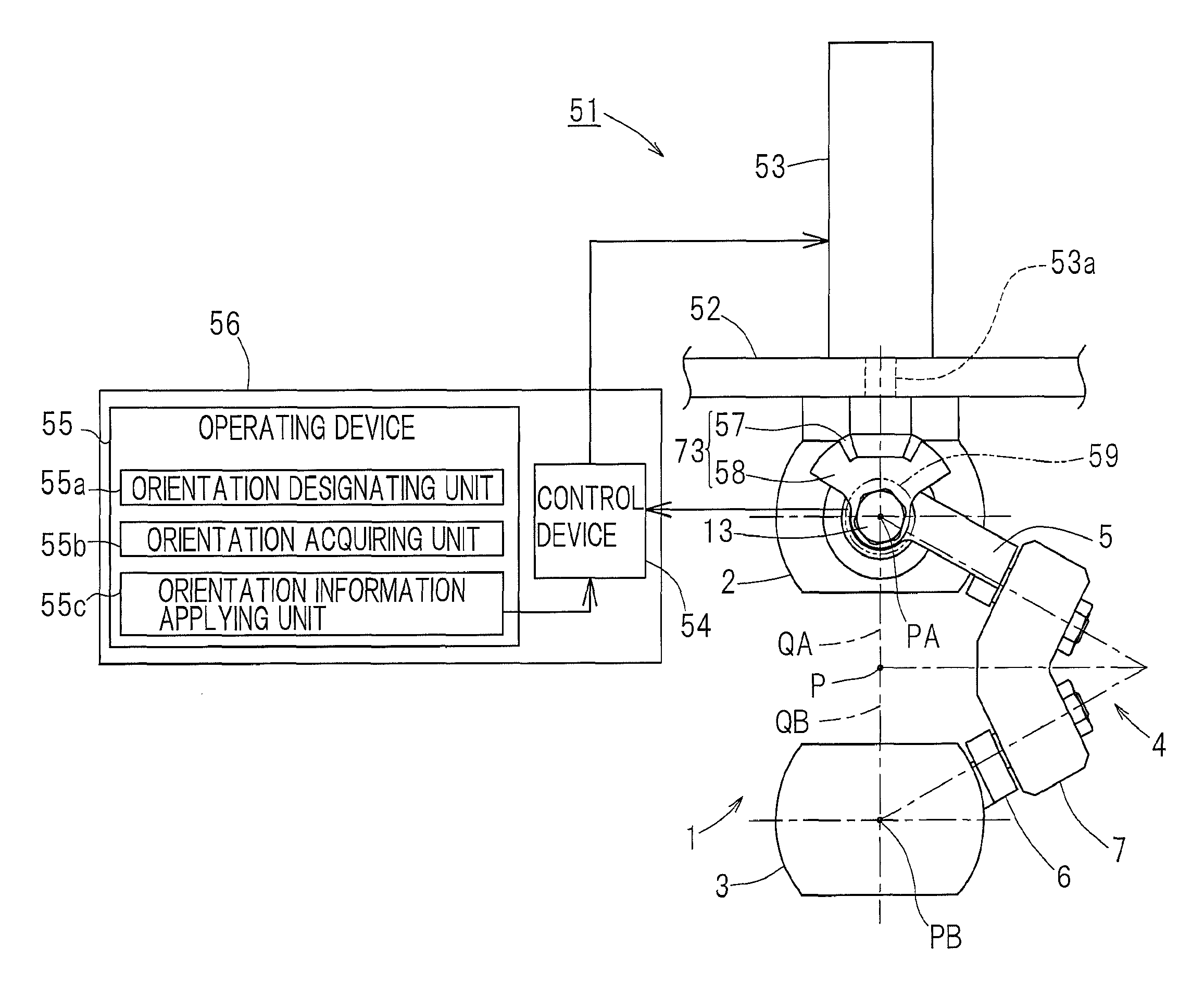
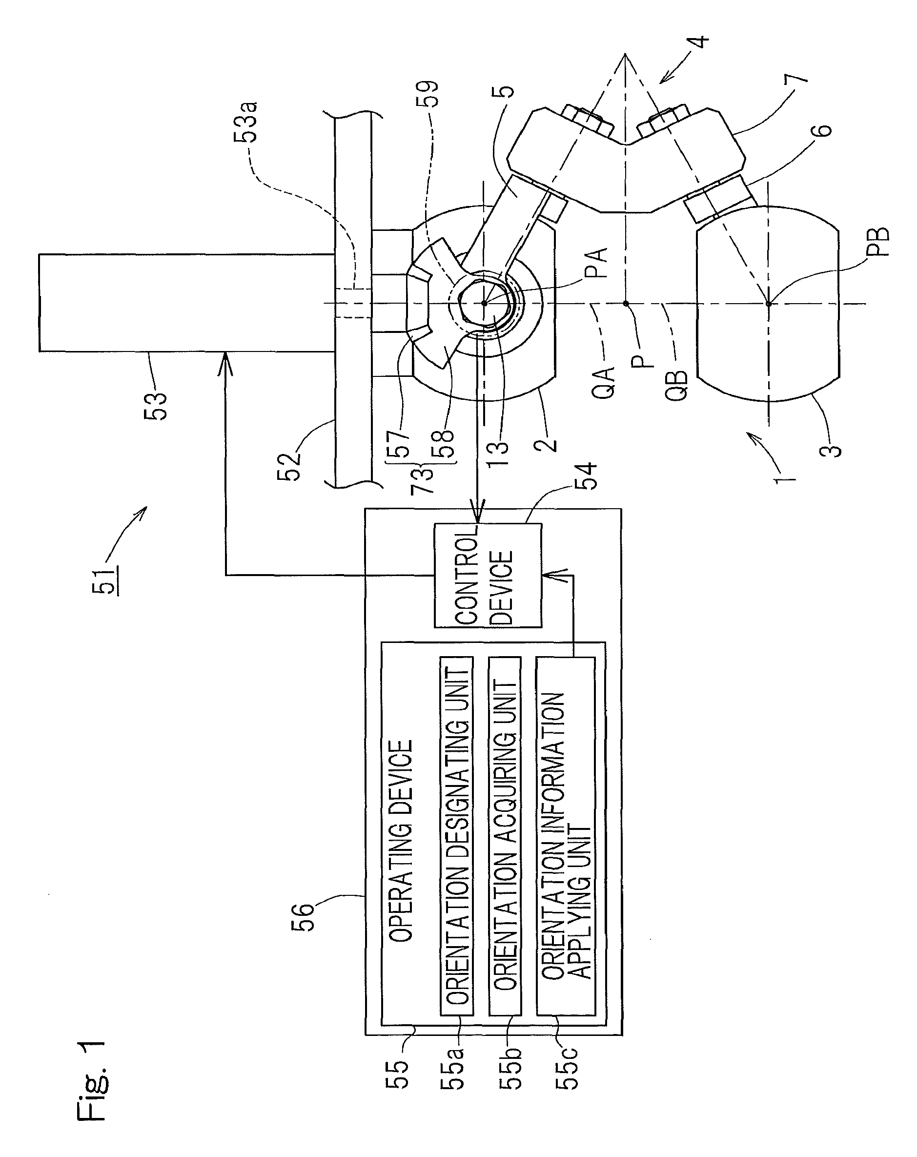
[0150]The gear type decelerating unit 73A includes a small gear 76, which is connected with an output shaft 70b of the actuator 70 through a coupling 75 in a rotation transmittable fashion, and a large gear 77 fixed to the proximal side end link member 5 and meshed with the small gear 76. In the second embodiment, each of the small gear 76 and the large gear 77 is in the form of a spur gear, and the large gear 77 is a sector shaped gear having teeth formed in a peripheral surface of the sector shape. The large gear 77 has the pitch circle radius that is greater than that of the small gear 76, and the rotation of the output shaft 70b of the actuator 70 is reduced to a rotational axis O1 of the revolve pairing portion T1 between the proximal end side link hub 2 and the proximal side end link member 5 and then transmitted to the proximal side end link member 5. The gear ratio thereof is rendered to be larger than 10.
[0151]The pitch circle radius of the large gear 77 is equal to or grea...
sixth embodiment
[0170]According to the above described construction in accordance with the sixth embodiment, since a portion on one side of the fixing member 205 in the parallel link member 1 adjacent the distal end side is extensively covered by the lubricant recovery member 200, the lubricant then scattered from the parallel link mechanism 1 and the decelerating unit 73 during the operation can be received by the lubricant recovery member 200. Since the projection 206 is provided in an outer peripheral end on the fixing member 205, even though the lubricant falls onto the fixing member 205, such lubricant will not fall outside the fixing member 205 and, therefore, the possibility of the work to be processed being wetted with the lubricant can be avoided. Since the connecting portion 208 is stretchable, even though the orientation of the distal end side link hub 3 relative to the proximal end side link hub 2 changes, the connecting portion 208 of the lubricant recovery member 200 can deform in res...
eighth embodiment
[0172]FIG. 19 illustrates the eighth preferred embodiment of the present invention. The link actuation device 51 of the eighth embodiment includes a lubricant recovery member 210 for receiving the lubricant falling downwardly from the bevel gears 57 and 58 of the decelerating unit 73. The lubricant recovery member 210 is of a dish-like member having a plate shaped portion 211, positioned immediately below the decelerating unit 73, and a projecting portion 212 protruding from an outer peripheral edge of the plate shaped portion 211 towards the base member 52. The lubricant recovery member 210 is fitted to the base member 52 by means of a bolt (not shown) through a mounting portion 213 linked with a portion of the projecting portion 212. This lubricant recovery member 210 is prepared from, for example, sheet metal.
[0173]The use of the lubricant recovery member 210 of such a structure as hereinabove described is effective to avoid the possibility that the lubricant falling from the dec...
PUM
 Abstract
Description
Claims
Application Information
 - R&D
- Intellectual Property
- Life Sciences
- Materials
- Tech Scout
- Unparalleled Data Quality
- Higher Quality Content
- 60% Fewer Hallucinations
Browse by: Latest US Patents, China's latest patents, Technical Efficacy Thesaurus, Application Domain, Technology Topic, Popular Technical Reports.
© 2025 PatSnap. All rights reserved.Legal|Privacy policy|Modern Slavery Act Transparency Statement|Sitemap|About US| Contact US: help@patsnap.com


