Sweep-based membrane separation process for removing carbon dioxide from exhaust gases generated by multiple combustion sources

a technology of exhaust gas and membrane separation, which is applied in the direction of separation process, emission prevention, combustion types, etc., can solve the problems of increasing the cost of capital investment, affecting the environmental protection of the environment,

Active Publication Date: 2017-01-17
MEMBRANE TECH & RES
View PDF39 Cites 6 Cited by
  • Summary
  • Abstract
  • Description
  • Claims
  • Application Information

AI Technical Summary

Problems solved by technology

Exhaust gases from many combustion processes are contaminated with carbon dioxide when emitted into the atmosphere, which contributes to global warming and environmental damage.
Such gas streams are difficult to treat in ways that are both technically and economically practical.
As such, implementing multiple carbon capture systems to treat the exhaust streams from each combustion source would be expensive and capital intensive.
However, even after the boiler has been modified to work with this oxygen content, the plant will suffer a 1-2% reduction in efficiency.
Similarly, natural gas power turbines can operate with as little as 15% oxygen, but again, a reduction in power output results.
In this way, the cost of modifying the combustion unit and the loss in efficiency mentioned above would only be incurred by one combustion unit although the carbon dioxide would be captured from several.

Method used


Image

  • Sweep-based membrane separation process for removing carbon dioxide from exhaust gases generated by multiple combustion sources
  • Sweep-based membrane separation process for removing carbon dioxide from exhaust gases generated by multiple combustion sources
  • Sweep-based membrane separation process for removing carbon dioxide from exhaust gases generated by multiple combustion sources

Examples


example 1

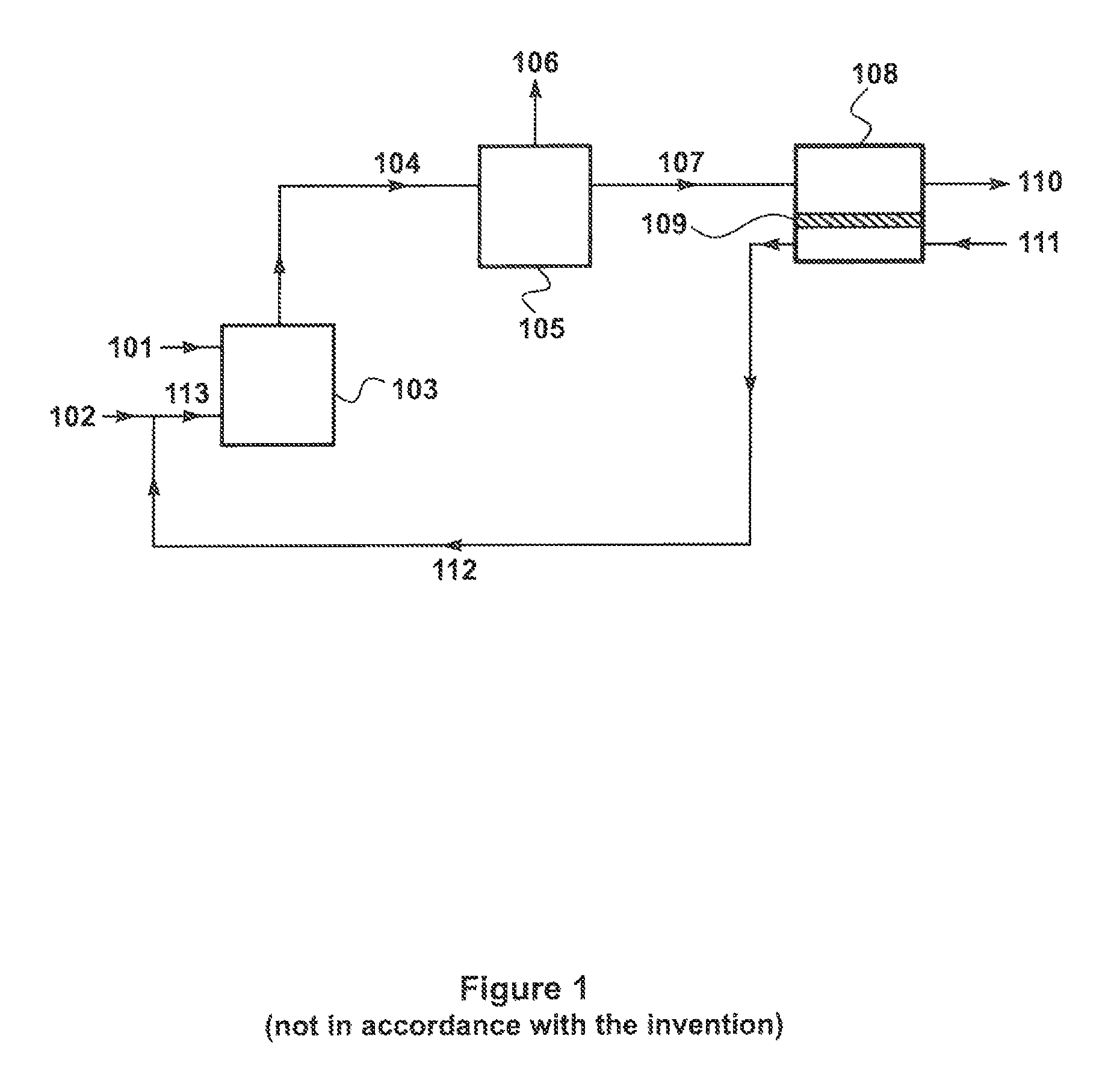
Combustion Process with No Carbon Capture or Sweep-Based Membrane Separation (not in Accordance with the Invention)

[0151]As a comparative example, a computer calculation was performed to determine the chemical composition of untreated exhaust gas from a steam boiler. The exhaust gas was cooled to 30° C. at atmospheric pressure to remove some of the water vapor, which was then emitted into the atmosphere. Results are shown in Table 1.

[0152]

TABLE 1Exhaust GasCondensedCooled Gas Streamfrom BoilerWater VaporExhaust GasTotal Flow6,5807745,800(m3 / h)Pressure1.01.01.0(bara)Temp (° C.)1804040Component (mol %)H2O15.599.94.2N272.9—82.5O23.9—4.4CO27.7—8.8

[0153]One boiler emits about 1 ton / h of carbon dioxide (2 ton / h of carbon dioxide for two boilers). The cooled exhaust gas has a concentration of about 8.8 mol % carbon dioxide.

example 2

Combustion Process with Sweep-Based Membrane Separation According to FIG. 1 (not in Accordance with the Invention)

[0154]A computer calculation was performed to determine the composition of the process streams from just one boiler. Because the boiler exhausts were treated separately, two capture systems were needed, one for each boiler.

[0155]Prior to the carbon capture step, the exhaust stream, 104, is cooled and pressurized from 1.0 to 1.1 bara with a blower to circulate the gas through the process (not shown in the figure).

[0156]The results of the calculation are show in Table 2.

[0157]

TABLE 2BoilerCO2Off-VentPermeateExhaustConcentrateGasGasStreamGas Stream(104)(106)(107)(110)(112)Total Flow8,0603327,7306,2408,490(m3 / h)Pressure1.10.21.11.00.9(bara)Temp (° C.)4040403040Component (mol %)H2O42.215.83.70.53.0N271.419.673.681.667.8O23.21.73.27.115.0CO221.263.019.44.814.2

[0158]The calculated membrane area and net energy required for one of the two boiler capture units employed were as fol...

example 3

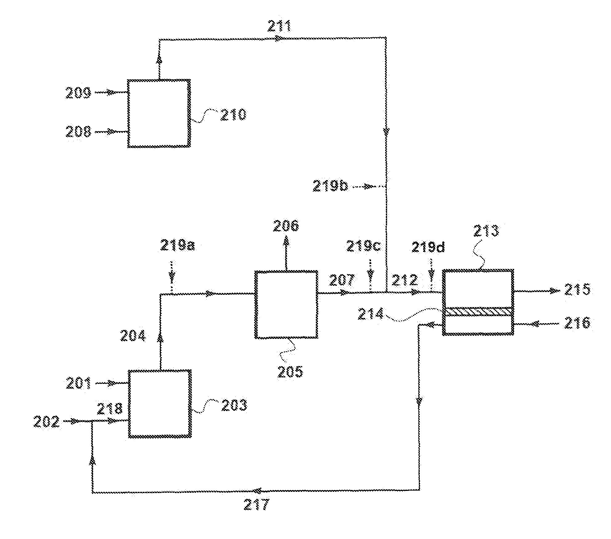
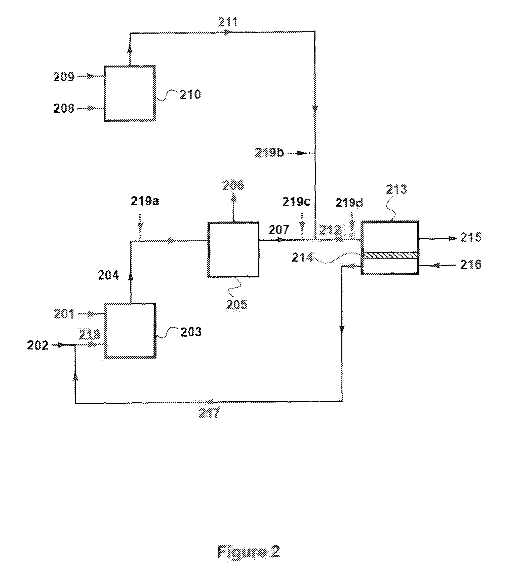
Combustion Process with Sweep-Based Membrane Separation According to FIG. 2

[0162]A calculation was performed to illustrate the treatment of exhaust gases from two boilers using a single capture unit as illustrated in FIG. 2. The results of the calculation are shown in Table 3.

[0163]

TABLE 3FirstCO2SecondMixedPermeateExhaustConcentrateOff-gasExhaustGasVent GasStreamGas Stream(204)(206)(207)(211)(212)(215)(217)Total flow (m3 / h)8,0107607,2505,93013,19011,9108,490Pressure (bara)1.10.21.11.11.11.00.9Temp (° C.)40404045423542Component (mol %)H2O4.215.53.13.93.41.23.6N275.228.180.182.781.387.370.9O23.22.23.34.84.06.415.0CO217.454.213.68.611.35.110.5

[0164]Compared Example 2, the total membrane area required for this process is reduced by 27% to 7,250 m2 per ton of carbon dioxide separated. The energy consumption is also reduced to 175 kW per ton of carbon dioxide separated.

[0165]The concentrated carbon dioxide stream, 206, is enriched in carbon dioxide to a concentration of 54 mol % carbon d...


PUM

PropertyMeasurementUnit
pressureaaaaaaaaaa
permeableaaaaaaaaaa
adsorptionaaaaaaaaaa

Abstract

A gas separation process for treating exhaust gases from multiple combustion sources. The invention involves directing an exhaust gas stream from one combustion step to a carbon capture step. An off-gas stream depleted in carbon dioxide from the carbon capture step is mixed with a second exhaust stream from a second combustion step to form a mixed gas stream. The mixed gas stream is passed as a feed stream across the feed side of a membrane that is selectively permeable to carbon dioxide over nitrogen and carbon dioxide over oxygen. A sweep gas stream, usually air, flows across the permeate side, and picks up the preferentially permeating carbon dioxide. The permeate stream withdrawn from the permeate side of the membrane is then recycled back to the combustor.

Description

FIELD OF THE INVENTION[0001]The invention relates to membrane-based gas separation processes, and specifically to sweep-based membrane separation processes to remove carbon dioxide from multiple exhaust gas streams produced from multiple combustion sources.BACKGROUND OF THE INVENTION[0002]Presented below is background information on certain aspects of the present invention as they may relate to technical features referred to in the detailed description, but not necessarily described in detail. The discussion below should not be construed as an admission as to the relevance of the information to the claimed invention or the prior art effect of the material described.[0003]Exhaust gases from many combustion processes are contaminated with carbon dioxide when emitted into the atmosphere, which contributes to global warming and environmental damage. Such gas streams are difficult to treat in ways that are both technically and economically practical.[0004]Gas separation by means of membr...

Claims


Application Information

Patent Timeline
Patent Type & Authority Patents(United States)
IPC IPC(8): B01D53/22F23L7/00B01D53/62F23J15/02B01D53/14
CPCF23J15/02B01D53/229B01D53/226F23L7/007B01D53/62B01D2258/0283B01D2257/504B01D53/1475B01D53/22F23J15/006B01D2053/224B01D2053/222F23J2215/50B01D53/002B01D53/04F23C6/02F23G5/006B01D53/225B01D2251/306B01D2251/606B01D2252/102B01D2252/20478B01D2253/102B01D2253/108Y02A50/20Y02C20/40Y02E20/32Y02E20/34
Inventor BAKER, RICHARD WMERKEL, TIMOTHY C.
Owner MEMBRANE TECH & RES
Why Eureka
Try Eureka