Class D audio amplifier with adjustable loop filter characteristics

a filter characteristic and audio amplifier technology, applied in the direction of dc amplifiers with modulator-demodulator, amplifiers with semiconductor devices/discharge tubes, low frequency amplifiers, etc., can solve the problem of unstable feedback loops, and achieve the effect of reducing the breakdown voltage requirements of individual semiconductor switches

Active Publication Date: 2017-02-07
INFINEON TECH AUSTRIA AG
View PDF13 Cites 37 Cited by
  • Summary
  • Abstract
  • Description
  • Claims
  • Application Information

AI Technical Summary

Benefits of technology

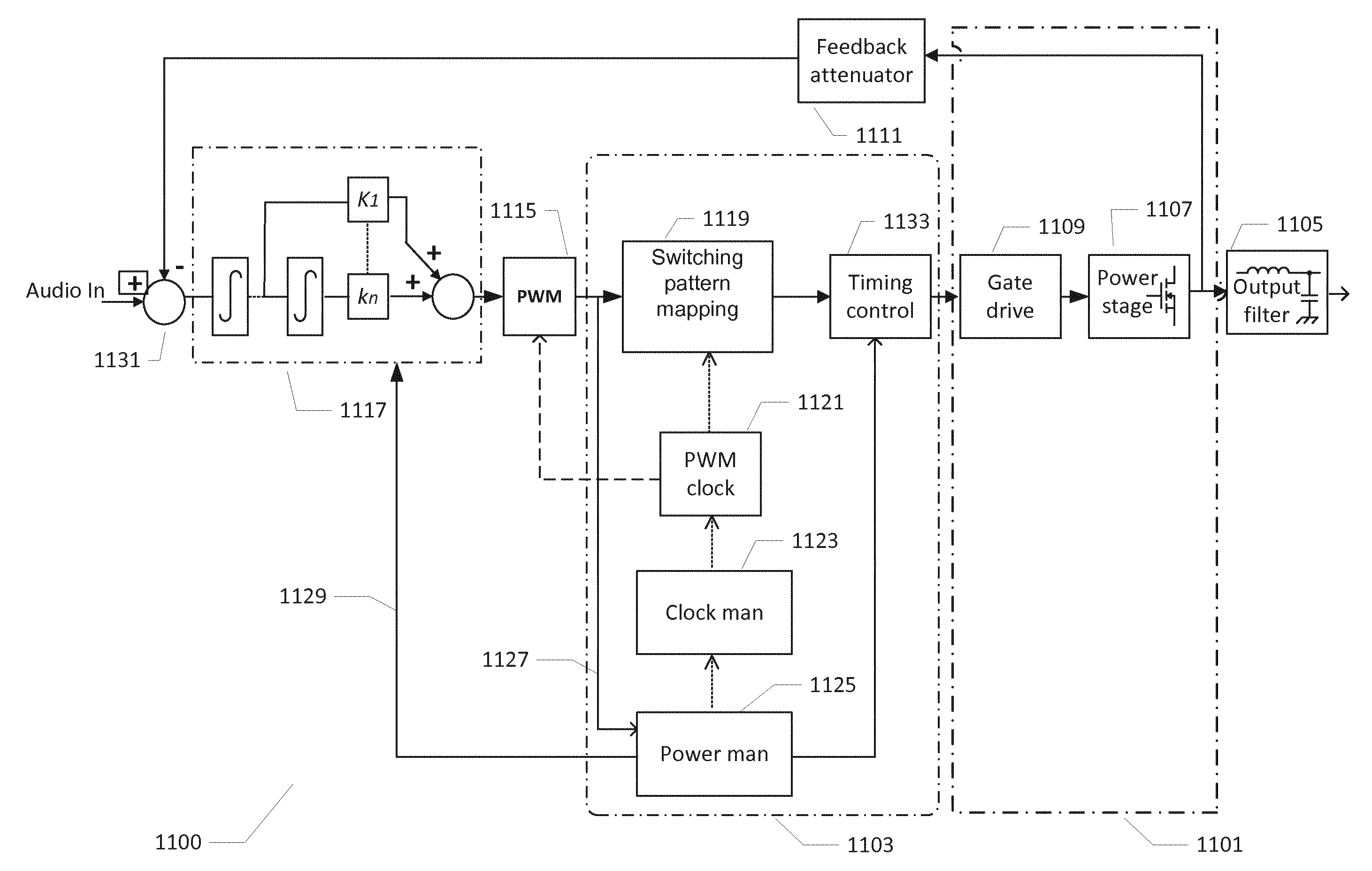
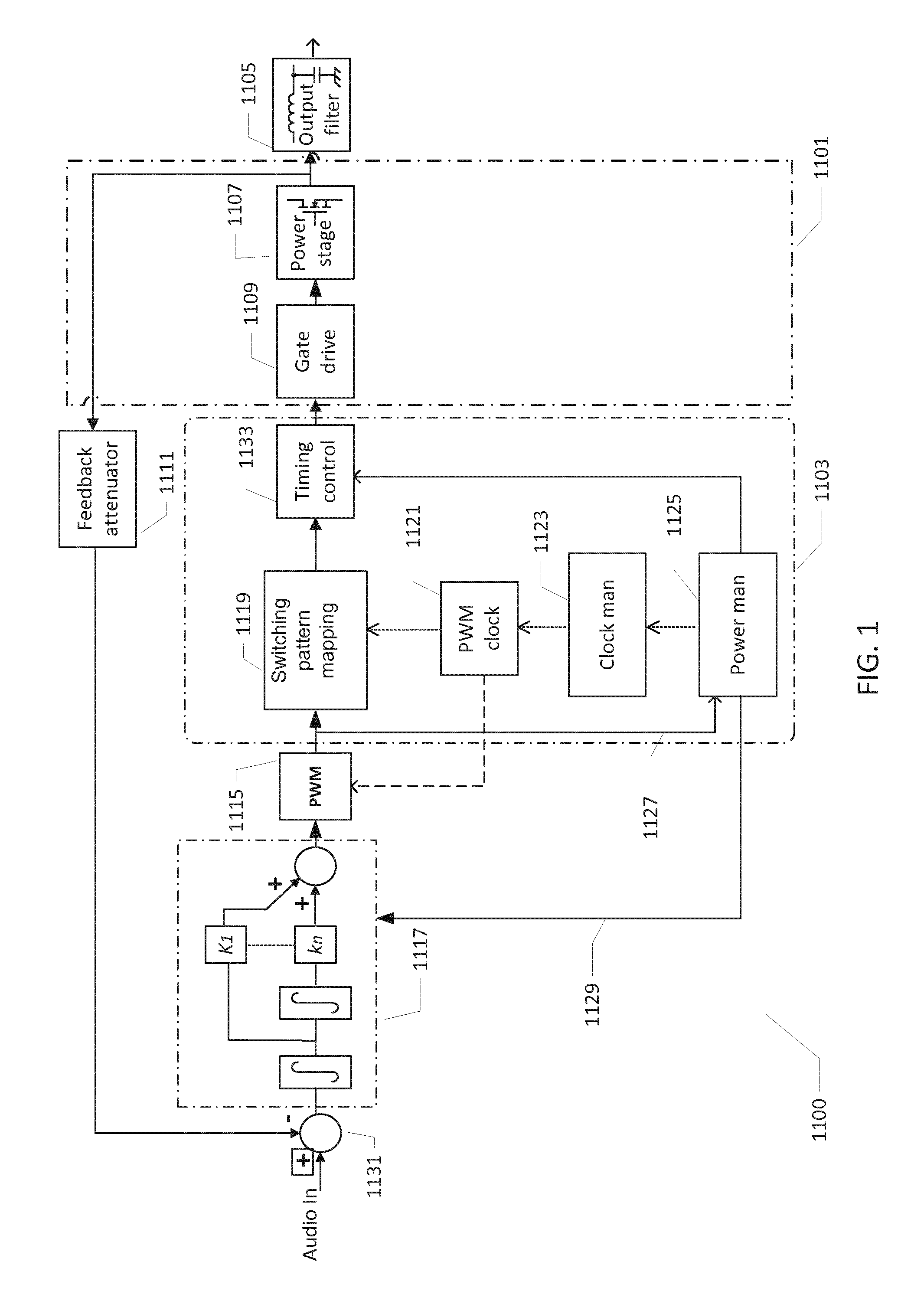
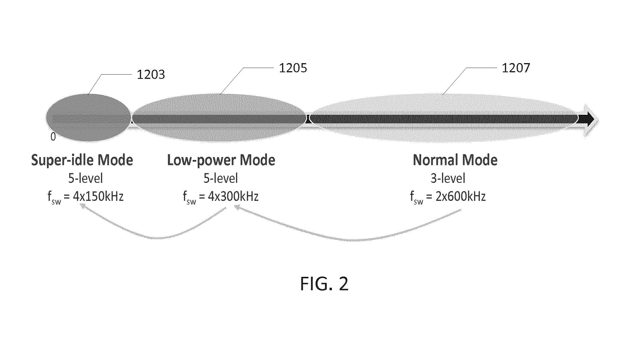
[0013]The controller is configured to control frequency response characteristics of the adjustable loop filter based on the frequency setting of the adjustable modulation frequency in accordance with the present invention. This is advantageous for various reasons as summarized in the following section. The frequency response characteristics of the loop filter is typically designed or selected such that the feedback loop of the class D amplifier remains just stable, within a required safety margin due to component spread and production spread, at the maximum setting of the adjustable modulation frequency. This loop filter design is advantageous in order to suppress distortion and noise generating mechanisms introduced by non-ideal behaviour of circuitry and components of the class D amplifier within the feedback loop. These distortion and noise generating mechanisms are complex and may be attributed to a variety of error sources such as timing errors in power transistors of the output driver, aliasing errors due to non-ideal frequency response of the feedback path and re-quantization errors etc. In general, output driver timing errors and aliasing errors tend to increase with increasing load on the class D amplifier or with increasing output power level of the class D amplifier. Error power induced by time quantization errors is proportional to the switching frequency or modulation frequency for a given digital sampling frequency. Therefore, the need for suppression of these types of errors and noise is most pronounced at the highest load power levels and at higher modulation frequencies e.g. at or close to the maximum setting of the adjustable modulation frequency. At smaller load power levels and at lower modulation frequencies it is often fully acceptable to set the frequency response characteristics of the adjustable loop filter such that less aggressive error and noise suppression is performed, i.e. expressed as a smaller magnitude of an error transfer function of the feedback loop within the audio bandwidth. However, the just stable design of the loop filter at the maximum setting of the adjustable modulation frequency together with the high load power level imply that the feedback loop inherently tends to become unstable when the controller selects a lower frequency setting than the maximum setting of the modulation frequency. This phenomenon is caused by the stable bandwidth of the feedback loop is limited to a certain fraction (1 / π for dual-edge naturally sampled PWM) of the modulation frequency. Hence, it is advantageous to tailor the frequency response characteristics of the adjustable loop filter to the actual or current setting of the modulation frequency, and optionally the load power level, to reach the highest possible loop gain in the audio bandwidth within loop stability constraints or bounds. This dynamic or adaptive adjustment of the frequency response characteristics of the loop filter leads to superior suppression of the above-mentioned error and noise mechanisms in the Class D audio amplifier at both the maximum and minimum frequency settings of the adjustable modulation frequency. In addition, any intermediate frequency setting(s) of the adjustable modulation frequency may be associated with a specifically tailored setting of the frequency response characteristics of the loop filter.
[0021]in a second state, connecting a second terminal of the capacitor to the first output node through the fourth and second semiconductor switches. It is a significant advantage of the latter embodiment that the DC voltage difference between the first and second supply voltages is divided between the at least two cascaded or series coupled semiconductor switches of the upper leg or the lower leg. The cascaded semiconductor switches reduce breakdown voltage requirements of the individual semiconductor switches.

Problems solved by technology

However, the just stable design of the loop filter at the maximum setting of the adjustable modulation implies the feedback loop tends to become unstable if a lower modulation frequency than the maximum frequency setting is chosen.

Method used


Image

  • Class D audio amplifier with adjustable loop filter characteristics
  • Class D audio amplifier with adjustable loop filter characteristics
  • Class D audio amplifier with adjustable loop filter characteristics

Examples


fourth embodiment

[0082]FIG. 14 is a schematic diagram of a class D audio amplifier with an H-bridge output driver comprising first and second output drivers 725, 726, respectively, coupled to a loudspeaker load 740 in accordance with the class D audio amplifier. The illustrated a class D audio amplifier also utilizes a multi-level balanced load signal. In the present embodiment, a first DC voltage source is configured to set a third supply voltage, preferably one-half of VS, at a first output node VA of a first output driver 725. A second DC voltage source is configured to set the third supply voltage, preferably one-half of VS, at a second output node VB of a second output driver 726. The first and second DC voltage sources comprises respective pairs of capacitive voltage dividers and semiconductor switches to generate one-half of VS voltage levels as explained below in further detail.

first embodiment

[0083]The topology of each of the output drivers 725, 726 is often referred to as a “neutral-point clamped” three-level half-bridge. A first load inductor 738 and a first load capacitor 722 is coupled between a first output node VA of the first driver 725 and a first terminal of the loudspeaker load 740 to form a lowpass filter. Another lowpass filter is formed by a second load inductor 737 and a second load capacitor 723 which are coupled between a second output node VB of the second driver 726 and a second terminal of the loudspeaker load 740. The purpose and characteristics of each of these lowpass filters are the same as those previously discussed in connection with output driver 401. The first output driver 725 comprises an upper leg with a first semiconductor switch SW2 coupled in series between a first supply voltage VS and a first output node VA of the first output driver. A second leg comprises a second semiconductor switch SW3 is coupled in series between GND, i.e. a secon...


PUM


Abstract

The present invention relates to a class D audio amplifier comprising a pulse width modulator, an adjustable loop filter and a feedback loop. The pulse width modulator generates a first set of pulse width modulated control signals at an adjustable modulation frequency for respective switch control terminals of a first output driver. A controller of the class D audio amplifier is configured to control frequency response characteristics of the adjustable loop filter based on a frequency setting of the adjustable modulation frequency.

Description

[0001]The present invention relates to a class D audio amplifier comprising a pulse width modulator, an adjustable loop filter and a feedback loop. The pulse width modulator generates a first set of pulse width modulated control signals at an adjustable modulation frequency for respective switch control terminals of a first output driver. A controller of the class D audio amplifier is configured to control frequency response characteristics of the adjustable loop filter based on a frequency setting of the adjustable modulation frequency.BACKGROUND OF THE INVENTION[0002]Class D audio amplifiers are a well-known type of audio power amplifier which is generally recognized to provide energy efficient audio drive of a loudspeaker load by switching a pulse width modulated (PWM) or pulse density modulated (PDM) signal across the loudspeaker load. Class D audio amplifiers typically comprises an H-bridge driver with a pair of output terminals coupled to respective sides or terminals of the l...

Claims


Application Information

Patent Timeline
Patent Type & Authority Patents(United States)
IPC IPC(8): H03F3/38H03F3/217H03F1/02H03F3/183
CPCH03F3/217H03F1/0205H03F3/183H03F2200/03H03F2200/351H02M7/4837
Inventor HOYERBY, MIKKEL
Owner INFINEON TECH AUSTRIA AG
Why Eureka
Try Eureka