Dual mode clock using a common resonator and associated method of use

Active Publication Date: 2017-02-28
INTEGRATED DEVICE TECH INC
View PDF118 Cites 1 Cited by
  • Summary
  • Abstract
  • Description
  • Claims
  • Application Information

AI Technical Summary

Benefits of technology

The present invention is a system and method that generates both a high performance clock signal and a low power clock signal using a common resonator. The low power clock is always present, even when the low power oscillator is disabled, and it can be programmed on-the-fly to enhance accuracy. The system is controlled with a single logic control line. This invention reduces the die area, cost, and board space and BOM cost while ensuring that the power consumption in the low power state is significantly small.

Problems solved by technology

However, in many systems, particularly those that are portable, when these high performance operations are not active, the system is said to be in a low power state or low power mode, when power saving is much more critical for overall battery life.
The kHz time keeping oscillator consumes low currents, but its low power (and hence limited gain) and high quality factor (Q) result in even longer startup times, which may not be acceptable in certain systems.
The use of two separate resonators and their respective load tuning capacitors consumes a considerable amount of board space and increases the bill of material cost of the device.
It is obvious that since the two different resonators at two different frequencies are used in these two different oscillators, their frequencies and phases may vary randomly over time, with respect to each other, further underscoring the synchronization difficulties in such systems between different clock domains.

Method used


Image

  • Dual mode clock using a common resonator and associated method of use
  • Dual mode clock using a common resonator and associated method of use
  • Dual mode clock using a common resonator and associated method of use

Examples


Embodiment Construction

[0019]Representative embodiments of the present invention are described below with reference to various examples wherein like reference numerals are used throughout the description and several view of the drawings to indicate like or corresponding parts and further wherein the various elements are not necessarily drawn to scale.

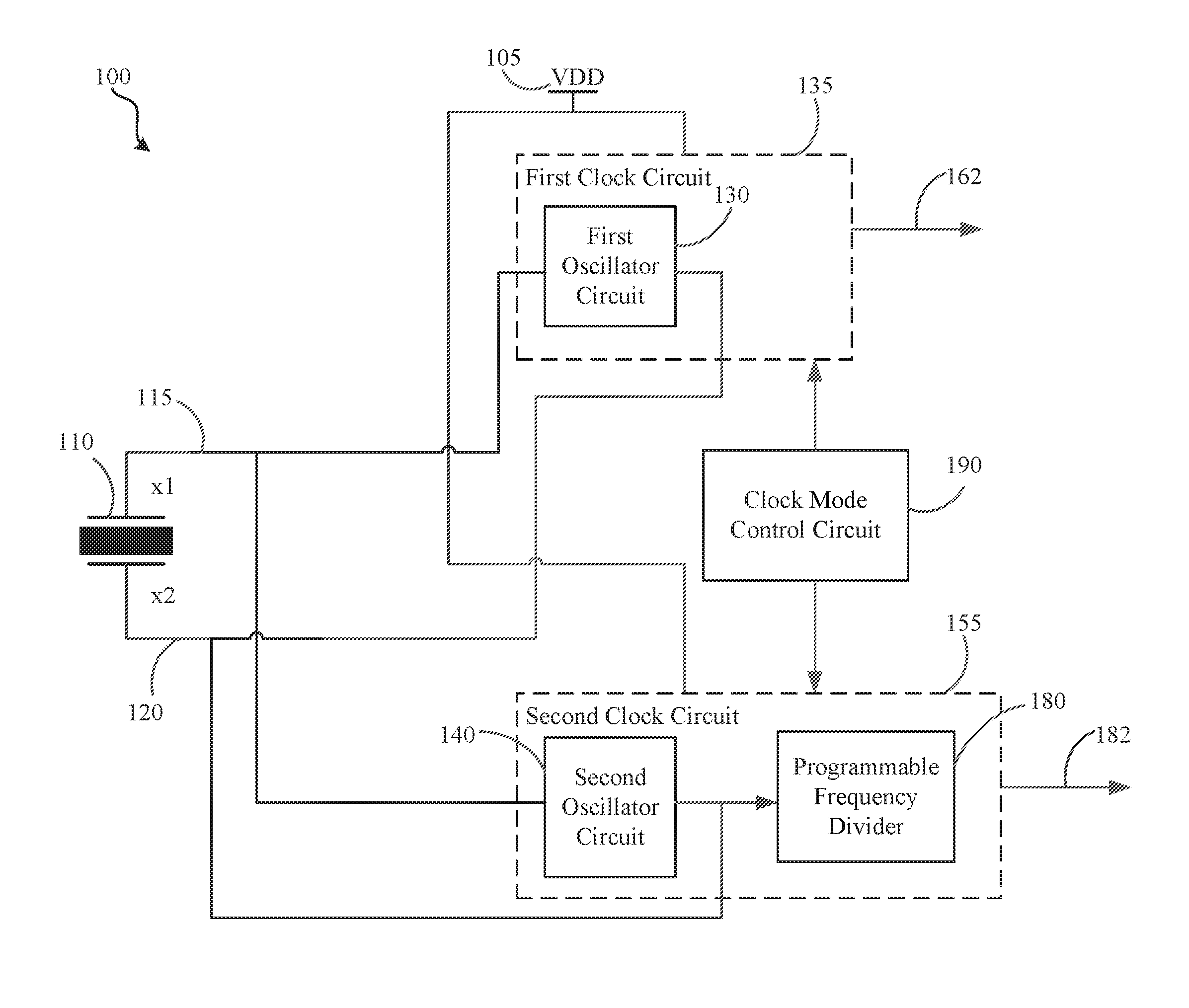
[0020]With reference to FIG. 1, an integrated circuit according to an embodiment of the present invention is illustrated and generally designated 100. In this exemplary embodiment 100, the present invention includes a resonator 110 having a resonant frequency that is presented across the outputs x1 115 and x2 120 of the resonator 110. In one embodiment, the resonator 110 may be a piezoelectric resonator, such as a crystal (quartz) resonator. Quartz resonators are well known in the art to provide a stable reference frequency for an integrated circuit. However, this is not meant to be limiting and the resonator may be one of various other resonators known in th...


PUM


Abstract

An integrated circuit comprising, a resonator, a first clock circuit for generating a first clock signal having a first frequency in response to the resonator, a second clock circuit for generating a second clock signal having a second frequency in response to the resonator, wherein the second frequency of the second clock signal is determined by the programmable frequency divider and a clock mode control circuit coupled to the first clock circuit and the second clock circuit, the clock mode control circuit for gradually switching the resonator between the first oscillator circuit and the second oscillator circuit of the integrated circuit, using a shift register based state machine and utilizing the inertia of the resonator to smoothly transition between the two oscillators, to provide a dual mode clock output signal.

Description

BACKGROUND OF THE INVENTION[0001]Most modern systems have well defined operating states, or modes of operation and most of these systems use one or more clocks. Typical high performance applications are locked to a crystal oscillator operating between 1 MHz to 100 MHz, which helps to perform important internal operations of the chip with low jitter and least timing uncertainty. However, in many systems, particularly those that are portable, when these high performance operations are not active, the system is said to be in a low power state or low power mode, when power saving is much more critical for overall battery life. Some systems may even have more than two such operating modes or states. Since the logic power consumption is directly proportional to the clock frequency, most systems use less than 100 KHz for low power time keeping operations, when the device is operating in a low power mode. It is desirable to shut down all system functionality when the device is operating in ...

Claims


Application Information

Patent Timeline
IPC IPC(8): G04F5/04H03B5/32H03K5/15
CPCG04F5/04H03K5/15006H03B5/32H03B2200/0082H03B5/364G04G3/02
Inventor GOYAL, PANKAJBAL, JAGDEEPAYCOCK, STEPHEN E.
Owner INTEGRATED DEVICE TECH INC
Why Eureka
Try Eureka