Pyrolysis and gasification systems, methods, and resultants derived therefrom

a gasification system and pyrolysis technology, applied in the field of pyrolysis systems and methods for producing gas products, can solve the problems of limiting the range of feedstocks that specific prior art pyrolysis systems may process, limiting the application range of specific prior art pyrolysis systems, and long-standing problems of obtaining consistency in pyrolysis products, etc., to achieve easy conformation, enhance the btu energy density of resultant gas, and enhance overall system efficiency

Active Publication Date: 2017-03-28
TUCKER RICHARD D
View PDF33 Cites 7 Cited by
  • Summary
  • Abstract
  • Description
  • Claims
  • Application Information

AI Technical Summary

Benefits of technology

[0015]It is an object of the present invention to overcome deficiencies in the prior art by providing processes, systems, and components for the pyrolysis and gasification of carbonaceous feedstocks to produce high quality resultant gases and high quality resultant Carbon products.

Problems solved by technology

However, obtaining consistency in the pyrolysis products has long been a problem.
Prior systems have attempted to pass a pyrolysis agent through a fluidized bed of solid; however, this requires a highly-granular and reactive fuel for pyrolysis, and, as such, is limited in its application.
Likewise, high and low-temperature pyrolysis processes are each better suited to pyrolizing different feedstocks, limiting the range of feedstocks that specific prior art pyrolysis systems may process.
Furthermore, though both high-temperature and low-temperature pyrolysis processes produce combustible, gases and materials, these resultant combustibles are often low grade, and they often contain harmful impurities, such as Mercury and Sulfur, that may contaminate the environment when these materials are combusted.
Furthermore, prior art systems do not provide efficient heat transfer to feedstocks, that exhibit multiple lobes in their specific heat signatures.
Furthermore, prior art pyrolysis systems and methods have been limited to “un-conditioned” resultant gas values of less than about 94% methane content and lack other typical requirements of natural gas companies for resultant gas injection directly into natural gas companies' distribution lines.
Furthermore, prior art pyrolysis systems and methods have overall efficiency challenges as the pure pyrolysis technologies are endothermic with the need for burners or other means of heat transfer into the pyrolysis reactor.
Furthermore, prior art pyrolysis systems and methods all disadvantageously directly couple and utilize feedstock feed mechanisms inside of and outside of the pyrolysis chamber(s) such that pyrolysis reactors must be increased or decreased in mass flow rate to avoid plugging problems and the like.
Furthermore, prior art pyrolysis systems and methods are not capable of producing very high BTU gas energy densities without separate chemical catalysis measures to produce the Methane content desired.
Furthermore, prior art pyrolysis systems and methods are not energy efficient in the removal of tars, liquors and other sticky and difficult condensable materials.
Furthermore, prior art pyrolysis systems and methods are incapable of or are deficient in producing in large scale from special Carbon products such as C60 Fullerenes, Carbon Nanotubes, Carbon Nano-wires and other Carbon Nano—structures all of which have greater value if the Carbon Nano—structures have particular length, number of walls and consistent structure.
Furthermore, prior art pyrolysis systems and methods are deficient in the elimination of entrained ambient air of soft, fluffy or compressible organic feedstocks.
Also, these prior art are deficient in the blocking of product gases from passing back through the feeder of the soft, fluffy or compressible organic feed stocks.

Method used


Image

  • Pyrolysis and gasification systems, methods, and resultants derived therefrom
  • Pyrolysis and gasification systems, methods, and resultants derived therefrom
  • Pyrolysis and gasification systems, methods, and resultants derived therefrom

Examples


Embodiment Construction

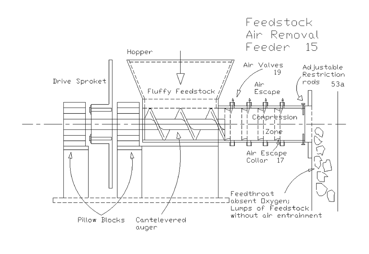
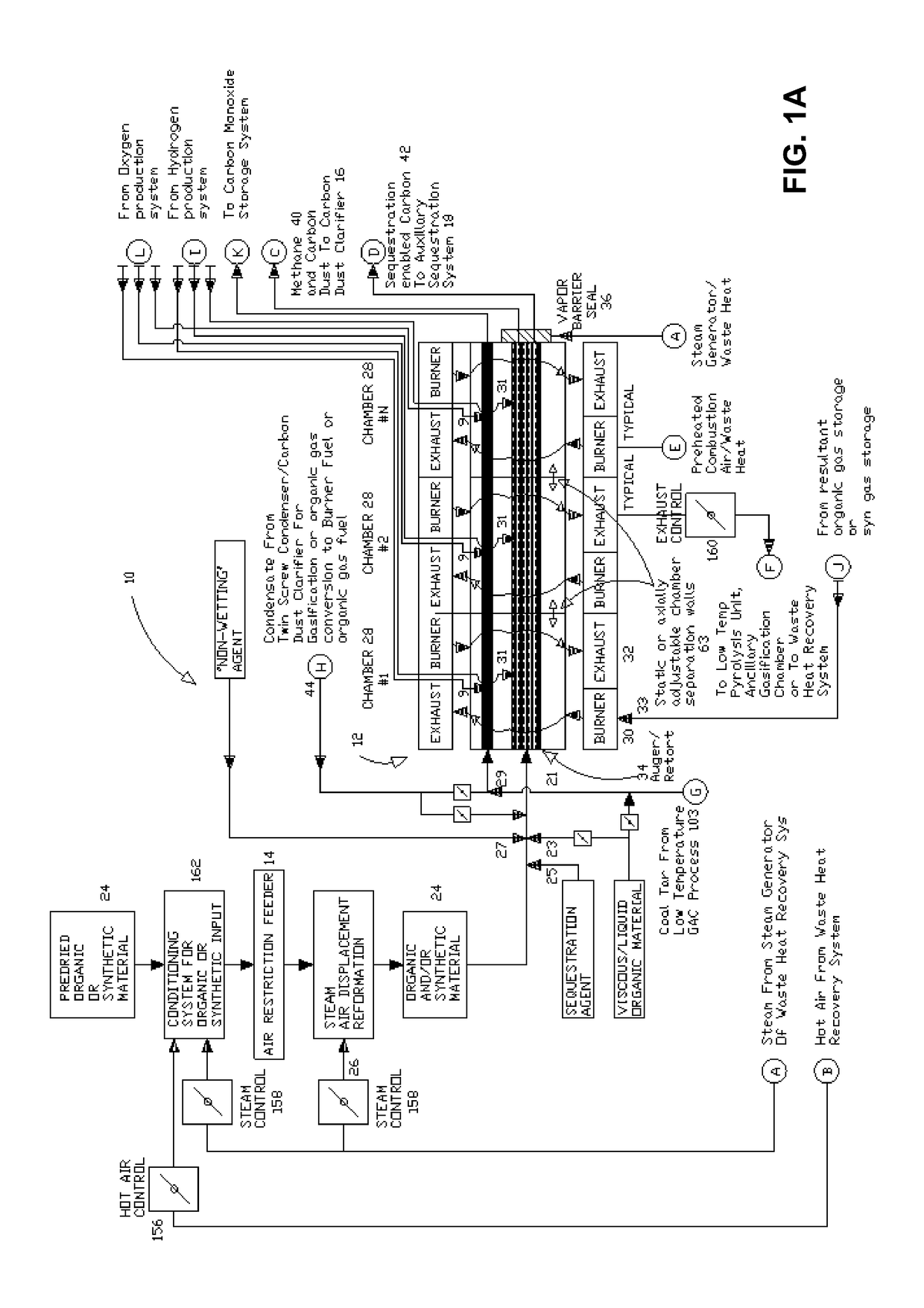
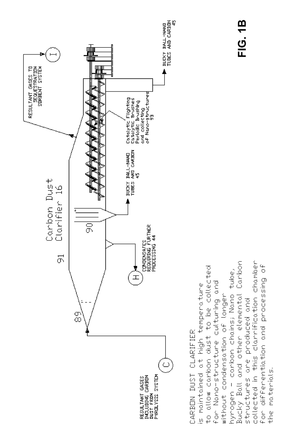
[0051]FIGS. 1A-1F are schematic diagrams showing components of a combined cycle carbonaceous feedstock conversion system 10 according to an exemplary embodiment of the present invention. The system 10 includes a high-temperature pyrolysis unit 12 that receives carbonaceous feedstock through an air restrictive airlock feeder 14 and / or an air removal feeder 15 with a sequestration agent injector 25 optionally providing a sequestration agent for the controlled internal sequestration of noxious elements and compounds that produce a substantially Mercury and Sulfur-free gas product containing methane and a solid product containing Carbon, activated Carbon, and Carbon Nano-Tubes, depending upon the type of feedstock and whether “non-wetting” agent injector 27 is used to induce non-wetting action. Exemplary sequestration agents include materials containing Halogen elements and exemplary non-wetting agents include materials containing silica. The system 10 includes further injectors of visc...


PUM

PropertyMeasurementUnit
temperaturesaaaaaaaaaa

Abstract

A process and system for the controlled thermal conversion of a carbonaceous feedstock, including: exposing the feedstock to one or more predetermined temperatures and one or more predetermined pressures for one or more predetermined amounts of time in one or more chambers to produce a gas product and a solid product, wherein the gas product includes one or more of methane, Carbon monoxide, Hydrogen, and one or more noxious chemicals and the solid product includes Carbon and Carbon nano-structures; sequestration enabling at least a portion of the Carbon by creating associated Lewis Acid Sites; sequestering at least one of the one or more noxious chemicals in the one or more chambers using the sequestration enabled Carbon; and controlling the constituents of the gas product using feedback, thereby providing a predictable and stable gas product from an unknown and / or variable feedstock and communicating data via SmartGrid communications protocols.

Description

CROSS-REFERENCE TO RELATED APPLICATIONS[0001]The present patent application / patent claims the benefit of priority of U.S. Provisional Patent Application No. 61 / 853,510, filed on Apr. 8, 2013, and entitled “PYROLYSIS AND GASIFICATION SYSTEMS, METHODS, AND RESULTANTS DERIVED THEREFROM,” the contents of which are incorporated in full by reference herein. The present patent application / patent is a continuation-in-part of U.S. Pat. No. 8,282,787, filed on Mar. 14, 2008, and entitled “PYROLYSIS SYSTEMS, METHODS, AND RESULTANTS DERIVED THEREFROM,” which claims the benefit of priority of U.S. Provisional Patent Application No. 60 / 906,691, filed on Mar. 14, 2007, and entitled “HIGH TEMPERATURE PYROLYSIS SYSTEM WITH ADVANCED OBNOXIOUS MATERIAL SEQUESTERING TO YIELD CLEAN METHANE AND CARBON RESULTANTS FROM ORGANIC AND SYNTHETIC COMPOUNDS,” U.S. Provisional Patent Application No. 60 / 997,791, filed on Oct. 3, 2007, and entitled “COMBINED CYCLE CONTINUOUS HIGH TEMPERATURE PYROLYSIS SYSTEM WITH AD...

Claims


Application Information

Patent Timeline
Patent Type & Authority Patents(United States)
IPC IPC(8): B01J19/14C10G1/10C10G1/02C10G1/00C10B53/04C10B53/02C10B47/30C10B53/00C10B47/44
CPCB01J19/14C01B31/02C01B31/0213C01B31/0226C10B47/30C10B47/44C10B53/00C10B53/02C10B53/04C10G1/002C10G1/02C10G1/10C10G2300/1003C10G2300/1011C10G2300/807Y02E50/14Y02P30/20C01B32/05C01B32/154C01B32/16Y02E50/10Y02P20/145
Inventor TUCKER, RICHARD D.
Owner TUCKER RICHARD D
Why Eureka
Try Eureka