Ultrasonic transducer assembly and system for monitoring structural integrity

a transducer and ultrasonic technology, applied in the direction of mechanical vibration separation, instruments, manufacturing tools, etc., can solve the problems of limiting affecting the economic impact of many industries, and the prediction of the life time of structures is often not accurate enough, so as to improve the durability and signal quality, improve the durability of the transducer assembly, and improve the durability of the signal quality

Active Publication Date: 2017-04-11
NAT RES COUNCIL OF CANADA
View PDF60 Cites 8 Cited by
  • Summary
  • Abstract
  • Description
  • Claims
  • Application Information

AI Technical Summary

Benefits of technology

[0012]A transducer assembly is provided for structural health monitoring, and the like, that improves the durability and signal quality while avoiding difficulties characterized with the prior art. While one substantial advantage of using a clamp is that substantially higher pressures can be applied, allowing a greater variety of couplants to be used for higher temperature applications, for example, the clamp with a flexible piezoelectric film has advantages even in low temperature applications without any couplant, improving durability of the transducer assembly, avoiding debonding, and improving signal quality and strength.
[0014]The transducer assembly is preferably flexible so that it may be clamped to curved surfaces, such as pipes, or pipe fittings (e.g. elbows, couplers, pipe joints, etc.) and other shaped components, especially those components that have sections that include convex surfaces. The materials chosen for construction of the transducer assembly may retain sufficient structural, electrical, and chemical integrity under severe harsh environments, such as high temperatures, making the assembly suitable for high temperature operation. For example, the piezoelectric film may have a composition consistent with fabrication using one or more layers of a mixture of a piezoelectric powder and organic precursors of dielectric and / or piezoelectric material. The resulting piezoelectric film may therefore have a level of porosity that improves flexibility, resistance to thermal shock and ultrasonic bandwidth.
[0019]A protective layer may surround the insulating layer. The clamp may be a band that serves as the protective layer. The clamp may be a tube clamp, comprising a deformable band for surrounding the section, formed of metal or a fibreglass textile, and may have a tensioning mechanism with a spring or spring washer to maintain a constant tension under different thermal conditions. More deformable band materials have superior conformability making them suited to components having more complex geometry.

Problems solved by technology

Corrosion, erosion, fatigue, creep are examples of degradation mechanisms that limit the life time of structures and cause significant economic impact on many industries.
The prediction of life time of structures is often not precise enough and inspection methods are regularly applied to structures to determine its health condition.
Structural health monitoring (SHM) of components of power plants, oil & gas and aerospace industries, such as pipes and other vehicle parts having respective contoured surfaces is desirable, but tricky.
Access to the structural parts to be inspected may be difficult due, for example, to safety concerns for inspectors, or to a limited access to the structure surface due to thermal insulation, adjacent mechanisms, electrical, pneumatic or hydraulic control lines, etc.
Furthermore, once access is provided, installing a sensor in a way that provides adequate contact between a piezoelectric material and the component to be tested, may be difficult.
The delay lines and cooling significantly limits the value of such transducers for widespread structural health monitoring.
Similar techniques have been used to separate ultrasonic transducers from high temperature surfaces and the separation, though perceived to be required for operation of the sensor, impairs the use of the sensor, and occupies a lot of space around the component.
Also in this previous art, the electrical connections are made by spring-loaded pins that are not practical for real industrial applications.
Other previous art that uses some kind of flexible transducers like U.S. Pat. No. 5,166,573 to Brown, for example, which teaches how to produce polymer-base FUTs and flexible UT arrays, but does not teach a practical assembly to attach to permanently monitor structures.
Also, as the piezoelectric layers of these transducers are polymer-based, they are inherently incapable of high temperature applications.

Method used


Image

  • Ultrasonic transducer assembly and system for monitoring structural integrity
  • Ultrasonic transducer assembly and system for monitoring structural integrity
  • Ultrasonic transducer assembly and system for monitoring structural integrity

Examples


Embodiment Construction

[0034]The following detailed description of embodiments refers to the accompanying drawings, which illustrate specific embodiments of the invention. This invention may, however, be embodied in different forms and should not be construed as limited to the embodiments set forth herein.

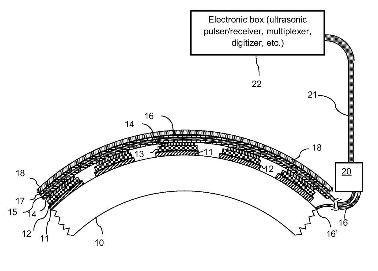
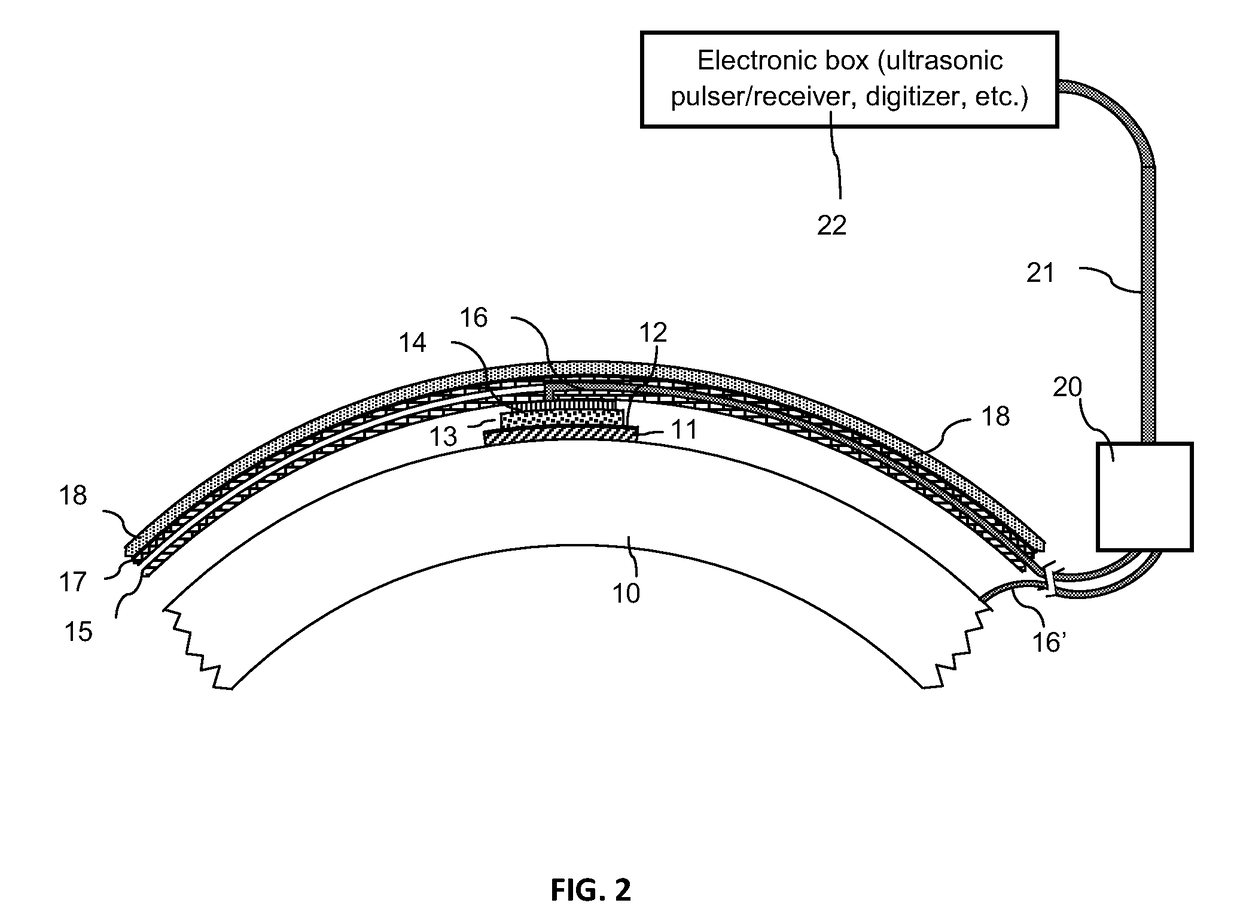
[0035]FIG. 1 is a schematic illustration of an example of the embodiment of multi-element ultrasonic transducer assembly for monitoring structural integrity. In this example a tube clamp 18 is used as a mechanically constraining layer. It embraces all other layers of the assembly and makes a robust attachment to the component to be monitored 10 represented by a tube in this example. Tube clamp 18 ensures good physical contact between layers of the transducer assembly where ultrasound need be transmitted. The transducer assembly is mounted on a pipe. Other common examples of components to be monitored include pipe fittings, and pressure vessels among others. In this example, a connection box 20 is used to...


PUM

PropertyMeasurementUnit
compressive stressaaaaaaaaaa

Abstract

In an ultrasonic transducer assembly, a conformable ultrasonic transducer has a piezoelectric layer and electrodes able to conform to curved surfaces, and a clamp for pressing the transducer into ultrasonic contact with a curved surface. Conformability is ensured with a thin, porous piezoelectric layer and suitable electrical conductors and insulators. The ultrasonic transducer may operate without further thermal shielding under harsh environments and / or at high temperatures.

Description

[0001]This application is a national phase entry of International Patent Application PCT / CA2011 / 001234 filed Nov. 7, 2011 and claims the benefit of United States Provisional Patent Application U.S. Ser. No. 61 / 410,473 filed Nov. 5, 2010, the entire contents which are herein incorporated by reference.FIELD OF THE INVENTION[0002]The present invention relates to an ultrasonic sensing assembly and system that is particularly useful for the monitoring of curved objects, including those that operate at high temperatures.BACKGROUND OF THE INVENTION[0003]Corrosion, erosion, fatigue, creep are examples of degradation mechanisms that limit the life time of structures and cause significant economic impact on many industries. The prediction of life time of structures is often not precise enough and inspection methods are regularly applied to structures to determine its health condition. Ultrasonics is one of the most valuable non-destructive testing methods to evaluate the condition of structur...

Claims


Application Information

Patent Timeline
Patent Type & Authority Patents(United States)
IPC IPC(8): B01B1/06G01N29/24G01N29/28B23P11/00G01N29/22
CPCG01N29/24B01B1/06B23P11/00G01N29/228G01N29/245G01N29/28G01N2291/0258G01N2291/265G01N2291/2634Y10T29/49966B06B1/0603G01N17/04
Inventor KRUGER, SILVIO E.
Owner NAT RES COUNCIL OF CANADA
Why Eureka
Try Eureka