Device and method for measuring ice thickness

a technology of ice thickness and measuring device, which is applied in the direction of mechanical measuring arrangement, instruments, and mechanical means, etc., can solve the problems of complex device, inability to handle important time aspects, and formation of cavity for electrodes in aircraft skin

Inactive Publication Date: 2017-04-18
SAAB AB
View PDF9 Cites 3 Cited by
  • Summary
  • Abstract
  • Description
  • Claims
  • Application Information

AI Technical Summary

Benefits of technology

[0010]The use of a differential detection where the output of the sensor is compared to a reference value provides for a short response time, i. e. ice accretion can be detected fast. Further, the accuracy of the measurements can be unchanged during the life time of the device due to the fact that the reference sensor arrangement is not exposed to the environment.
[0014]In one option, the processing unit comprises a lock-in amplifier (641) arranged to output the relation between the impedance value and the reference impedance value. The lock-in amplifier is arranged to receive the impedance value and the reference impedance value on its inputs. The lock-in amplifier is phase locked at the same frequency as the operating frequency of the sensor arrangement and the reference sensor arrangement. The use of a lock-in amplifier allows for high precision, resolution and accuracy. The fact that the lock-in amplifier only operates at one frequency provides for a high level of noise rejection. Further, the use of a differentially connected sensor arrangement and reference sensor arrangement measured by means of measured a lock-in amplifier enables measurements to acquire various levels of accreted thickness with discrimination down to a fraction of a millimeter. Thereby, ice rejection actuators can be activated at the right moment in time for the highly demanding conditions of modern aircrafts where ice accretion is not allowed to be larger than a few millimeters.
[0015]A Wheatstone bridge could be comprised in the processing unit; however, the lock-in amplifier offers the advantages of significant noise reduction.

Problems solved by technology

One disadvantage with the device described in U.S. Pat. No. 6,239,601 is that a cavity for the electrodes is formed in the aircraft skin.
Furthermore, the device is complex due to the use of a plurality of electrodes.
Thus, the important time aspect is not handled by the device.

Method used


Image

  • Device and method for measuring ice thickness
  • Device and method for measuring ice thickness
  • Device and method for measuring ice thickness

Examples


Embodiment Construction

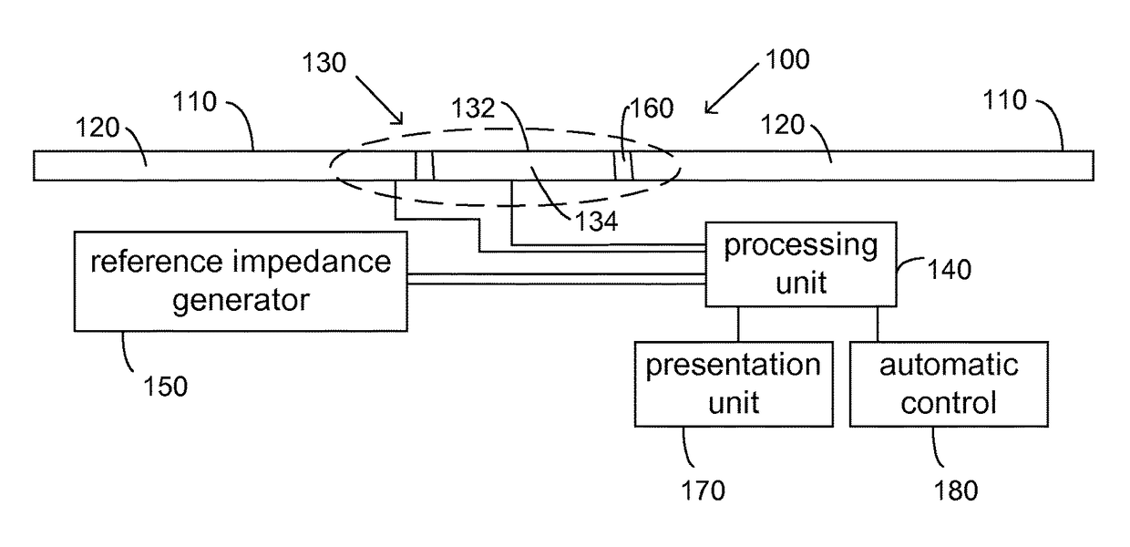
[0030]In FIG. 1, a device for measuring ice thickness 100 on a surface 110 of a construction element 120 is depicted. The construction element 120 comprises in one example a metal such as aluminium or an alloy thereof. In one example, the construction element 120 is the wings or fuselage of an airborne vehicle such as an airplane. Furthermore, the device for measuring ice thickness could be adapted to curve parts of wings, fuselage, engine air intake or any other point at which ice accretion monitoring is wanted. Each construction element 120 is provided with one or a plurality of devices for measuring ice thickness 100.

[0031]The construction element 120 can be used in many other applications, aeronautical or not. In one example, the construction element 120 is incorporated in a stationary application.

[0032]The operation of the device for measuring ice thickness 100 is based on the temperature dependence of the dielectric property tensor of ice while the detection of water, water wi...


PUM


Abstract

A device and method for measuring ice thickness on a first surface of a construction element. The device includes a sensor arrangement arranged in connection with the construction element and arranged to provide signals related to an impedance. A processing unit is coupled to the sensor arrangement and arranged to determine the presence of ice based on the provided impedance signals. A reference sensor arrangement is arranged to generate reference impedance measurement signals. The processing unit is further arranged to determine the ice thickness based on determinations of a relation between the impedance signals determined by the sensor arrangement and the reference impedance values generated by the reference sensor arrangement.

Description

CROSS-REFERENCE TO RELATED APPLICATIONS[0001]The application is the national phase under 35 U.S.C. §371 of PCT / SE2010 / 050774 filed 5 Jul. 2010.TECHNICAL FIELD[0002]The present invention relates to a device and method for measuring ice thickness on a surface of a construction element, said device comprising a sensor arrangement arranged in connection with said construction element and arranged to provide values related to an impedance.BACKGROUND ART[0003]It is known that water / ice exhibit a phase transition while passing through 0° C. In particular, the values of the dielectric properties exhibit a dramatic change as the temperature is lowered across the freezing point. Furthermore, the conductivity of liquid water changes dramatically with its ionic content. This allows for use for use of total impedance measurements to the presence of either water or ice on for example a surface of an aircraft skin.[0004]U.S. Pat. No. 6,239,601 describes a device and method for determining the thic...

Claims


Application Information

Patent Timeline
Patent Type & Authority Patents(United States)
IPC IPC(8): B64D15/20G01B7/06G08B19/02
CPCG01B7/06B64D15/20G08B19/02
Inventor FIGUEROA-KARLSTROM, EDUARDO
Owner SAAB AB
Why Eureka
Try Eureka