
60 GHz wideband class E/F2 power amplifier

a power amplifier and wideband technology, applied in the field of amplifier circuits, can solve the problems of poor efficiency of 60 ghz cmos radio power amplifiers, switching power amplifiers, and rare mm-wave frequencies of mm-wave frequencies, and achieve the effect of improving the overall bandwidth and systematic peak current of the final stag

Active Publication Date: 2017-04-25
SHORT CIRCUIT TECH LLC
View PDF9 Cites 5 Cited by
  • Summary
  • Abstract
  • Description
  • Claims
  • Application Information

AI Technical Summary

Benefits of technology

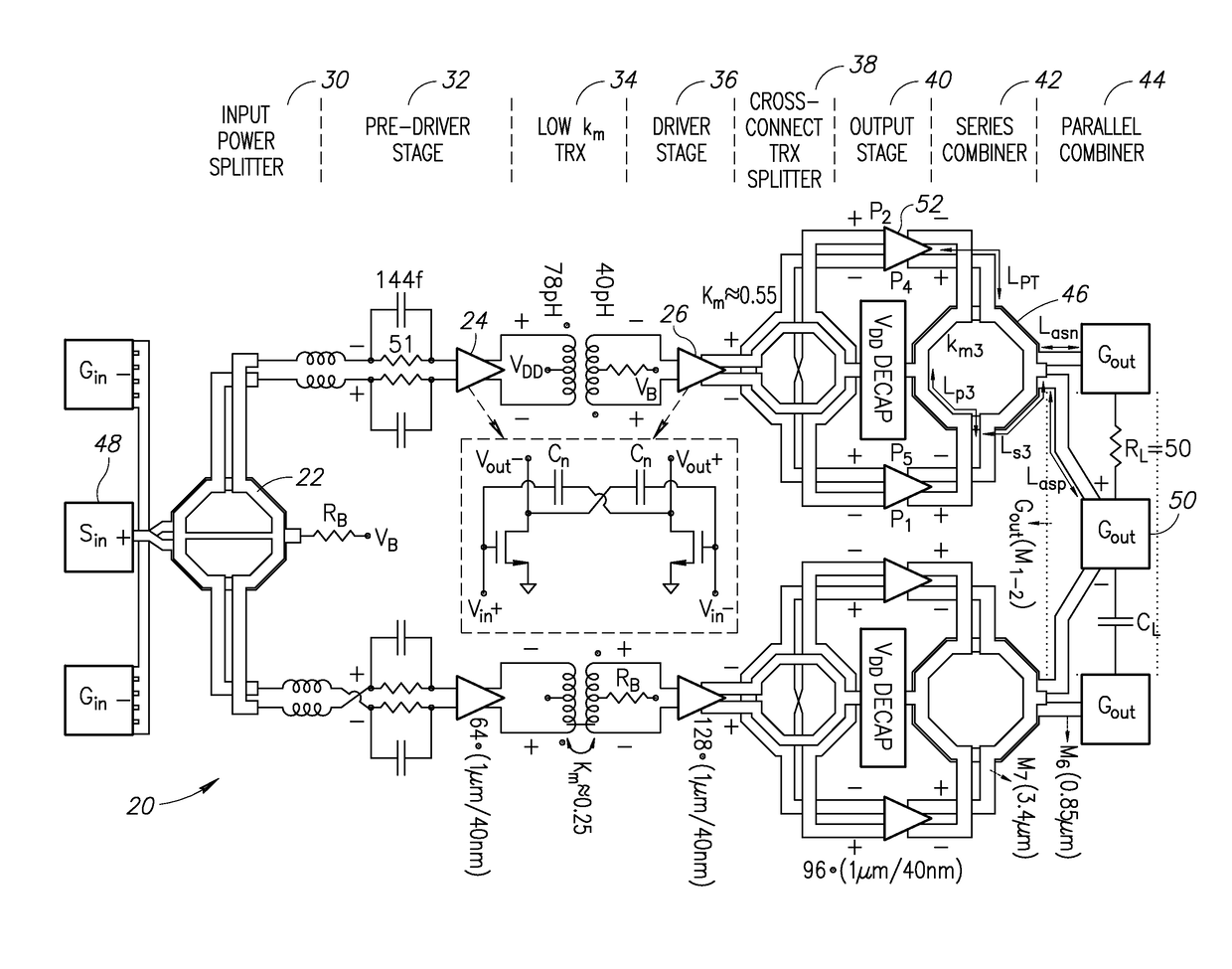
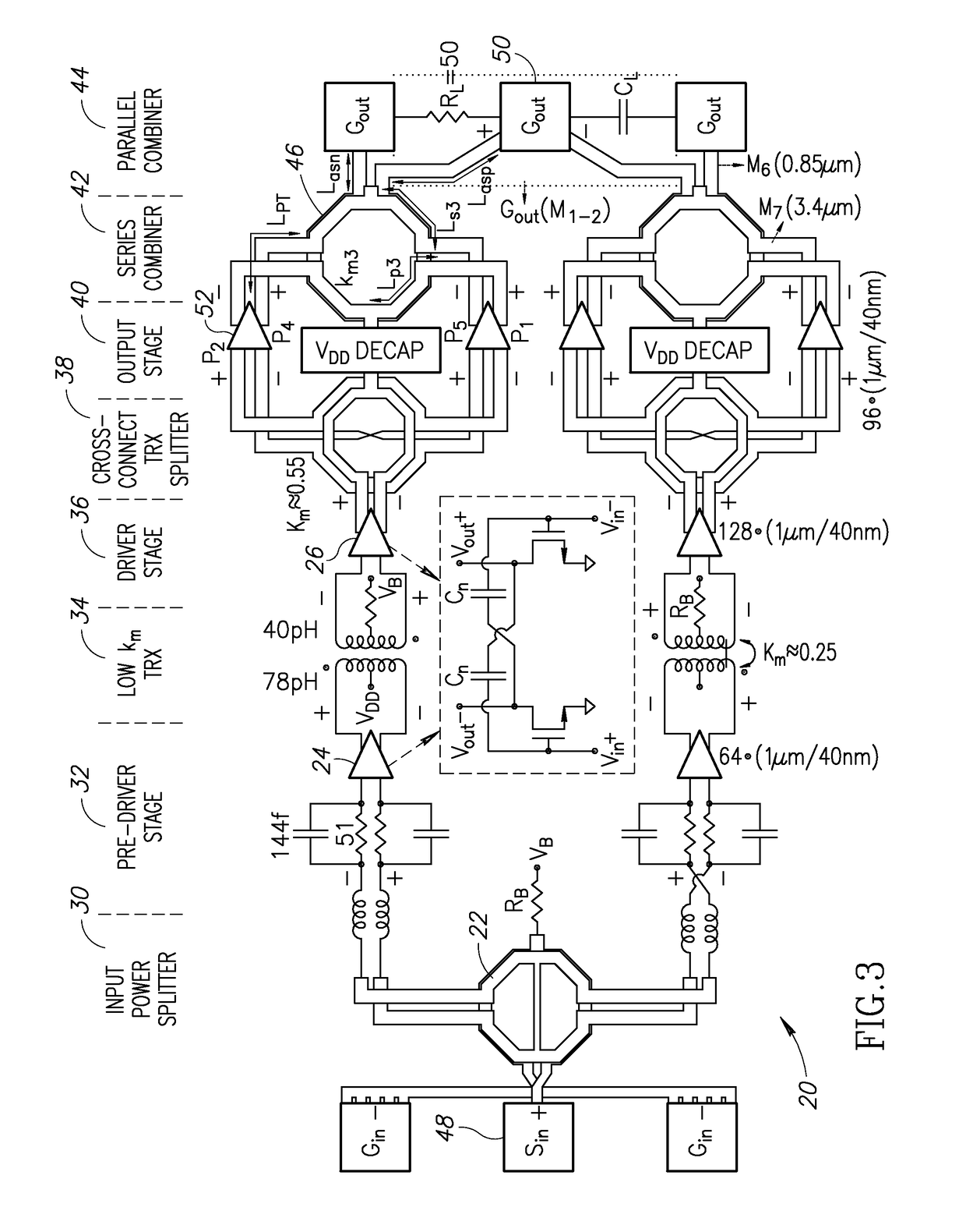
This patent presents a novel design for a switched-mode power amplifier of 60 GHz that is fully integrated. The invention reduces the peak current required for efficient operation, utilizing a second-harmonic termination and low / moderate magnetic coupling factors. The amplifier also takes advantage of the different behavior of the output impedance matching network for differential mode and common mode excitation. The invention also provides techniques to stabilize transformers against various modes of undesired oscillations. The power amplifier is stable against combined common mode and differential mode oscillations and can be used in a wide range of applications including mobile devices. The invention also includes a radio frequency signal splitter with improved bandwidth and reduced combined common mode and differential mode oscillations, and a class E / F2 power amplifier with reduced peak current and improved power added efficiency.

Problems solved by technology

Considering digital radios, a key technical challenge of 60 GHz CMOS radios is poor efficiency of their power amplifier (PA).
Switching power amplifiers, however, are rarely seen at mm-wave frequencies due to the large output capacitance and low current capability of CMOS transistors.

Method used


Image

  • 60 GHz wideband class E/F<sub>2 </sub>power amplifier
  • 60 GHz wideband class E/F<sub>2 </sub>power amplifier
  • 60 GHz wideband class E/F<sub>2 </sub>power amplifier

Examples


Embodiment Construction

Benefits and Constraints of Class-E / F Power Amplifier

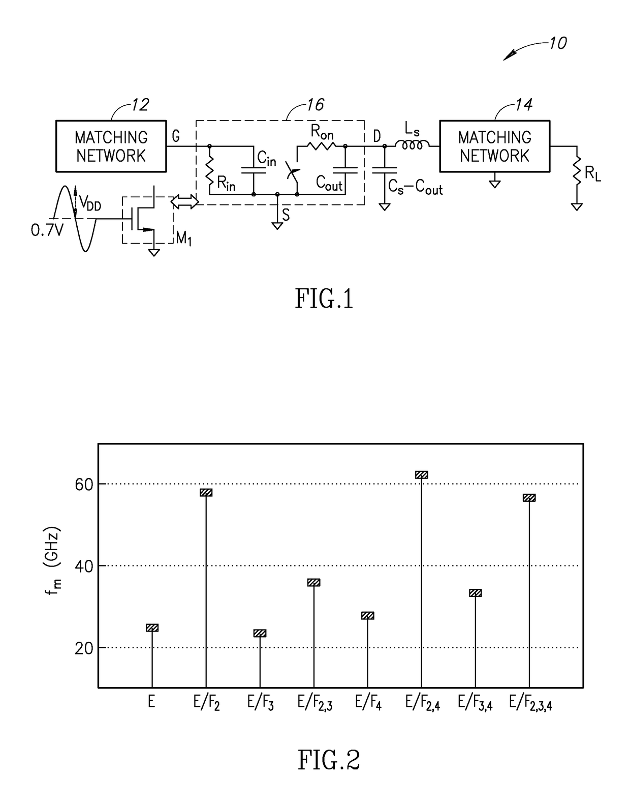
[0032]A high level schematic of an example class-E / F power amplifier is shown in FIG. 1. The circuit, generally referenced 10, comprises an input matching network 12, switch transistor M1 (modeled as equivalent circuit 16, capacitor Cs-Cout, inductor Ls and matching network 14 connected to the antenna load RL.

[0033]It can be shown that the drain efficiency ηD of zero-voltage switching (ZVS) PA 10 can be written in terms of a set of technology dependent parameters (Ron, Cout) and a set of matching network or waveform dependent parameters (FC, FPI, FI). Equation 1 below can be used to better understand the tradeoffs in mm-wave designs:

[0034]ηD=1-Ron⁢Irms2VDD⁢IDC=1-(IrmsIDC)2⁢IDCCS⁢ω0⁡(VDD-Vsat)·(VDD-VsatVDD)⁢(CSCout)⁢(Ron⁢Cout)⁢ω0.(1)

[0035]The waveform figures of merit (FoM) are defined as the following:

[0036]FI=IrmsIDC,(2)FC=IDCCS⁢ω0⁡(VDD-Vsat),(3)FPI=IpeakIDC.(4)

[0037]Where Ron and Cout are the on-state channel resistance and off-...


PUM

PropertyMeasurementUnit
insertion lossaaaaaaaaaa
voltageaaaaaaaaaa

Abstract

A novel and useful fully integrated switched-mode wideband 60 GHz power amplifier architecture. Using an appropriate second-harmonic termination of its output matching network, the required systematic peak current of the final stage is reduced such that the PA functions as a class-E / F2 switched-mode PA at saturation. In addition, low / moderate magnetic coupling factor transformers in the intermediate stages enable the PA to reach a high power added efficiency (PAE) and bandwidth product. Transformers of low / moderate coupling are also utilized in the preliminary stages of the PA to improve the overall bandwidth. In addition, the PA exploits the different behavior of the output impedance matching network for differential mode (DM) and common mode (CM) excitations. The PA is also stabilized against the combination of DM and CM oscillation modes. The PA also provides a technique to stabilize transformer-based mm-wave amplifiers against various modes of undesired oscillations.

Description

REFERENCE TO PRIORITY APPLICATION[0001]This application claims priority to U.S. Provisional Application Ser. No. 62 / 059,448, filed Oct. 3, 2014, entitled “Power Amplifier,” incorporated herein by reference in its entirety.FIELD OF THE INVENTION[0002]The present invention relates generally to amplifier circuits and in particular to a 60 GHz wideband class E / F2 power amplifier.BACKGROUND OF THE INVENTION[0003]Radio frequency (RF) power amplifier is a key component of radios that functions to convert a low power RF signal into a larger signal having significant power for driving, for example, the antenna of a transmitter. As more and more of the radio processing chain goes digital, there is currently great effort to digitize and integrate the PA, which traditionally was implemented off-chip with discrete analog components.[0004]Considering digital radios, a key technical challenge of 60 GHz CMOS radios is poor efficiency of their power amplifier (PA). By using advanced digitally intens...

Claims


Application Information

Patent Timeline
Patent Type & Authority Patents(United States)
IPC IPC(8): H03F3/60H03H7/38H01F27/29H03F3/217H03F3/21H03F3/193H03F1/56H01F27/28H03F3/24H03F1/02H01Q1/50H03H7/40
CPCH01F27/2823H01F27/29H01Q1/50H03F1/565H03F3/193H03F1/0205H03F3/211H03F3/2171H03F3/2176H03F3/245H03H7/38H03H7/40H03F2200/318H03F2200/451H03F2200/534H03F2200/537H03F2200/541H03F2203/21106H03F2203/21139H03H7/09H03H7/425H03H7/427H03H7/48
Inventor BABAIE, MASOUDSTASZEWSKI, ROBERT BOGDAN
Owner SHORT CIRCUIT TECH LLC
Learn More