
Power wafer

a technology of power wafers and wafers, which is applied in the direction of sustainable manufacturing/processing, battery technology, cell components, etc., can solve the problems of limited materials, increased energy, and corresponding advancements in battery technology, and achieve the effect of increasing energy storag

Active Publication Date: 2017-05-09
TRION ENERGY SOLUTIONS CORP
View PDF85 Cites 1 Cited by
  • Summary
  • Abstract
  • Description
  • Claims
  • Application Information

AI Technical Summary

Benefits of technology

The patent text discusses the use of conductive infusions in power wafers to overcome the limitations of conventional batteries. These infusions can increase charging times and decrease performance caused by wire and soldered connections. They also allow for the use of materials and methods that would be incompatible with wire and soldered connections. The alignment of carbon nanotubes in the power wafer further enhances charge distribution and increases electrical conductivity. The addition of magnetically-sensitive metal or metal oxide to the carbon nanotubes can make them responsive to a magnetic field. The use of conductive infusions with aligned carbon nanotubes can provide greater electric current densities than metals like copper. The power wafer can be built using conventional wire or wire-like materials and applicable connection techniques.

Problems solved by technology

Unfortunately while these devices have become significantly more powerful and as a result require an increasing amount of energy to run, there have been few corresponding advancements in battery technology.
The use of these wires has limited the type of materials that can be utilized for the cathode and anode.
Furthermore, since it has been shown that the electron transfer radiates on the anode and cathode plates from the point of attachment, the wires are attached at a single point, they can bottleneck, or at least impede, the electron transfer involved in recharging or discharging a battery.
Again, in traditional batteries this has been accomplished by connecting battery plates internally via single-point solder joints or conductive-element-filled epoxies to a plurality of wires which limits the type of materials that can be utilized for the cathode and anode, and creates a bottleneck with respect to the electron transfer involved in recharging or discharging a battery.
While other materials have shown promise in replacing lithium materials in rechargeable batteries, current battery structures limit their applicability.
Due to a limited ability to make an effective wired connection to each battery plate and, since such battery cells have traditionally been connected internally via single-point solder joints or conductive-element-filled epoxies to a plurality of wires, this has limited the use of some alternative materials as well as limiting the charge and discharge current.

Method used

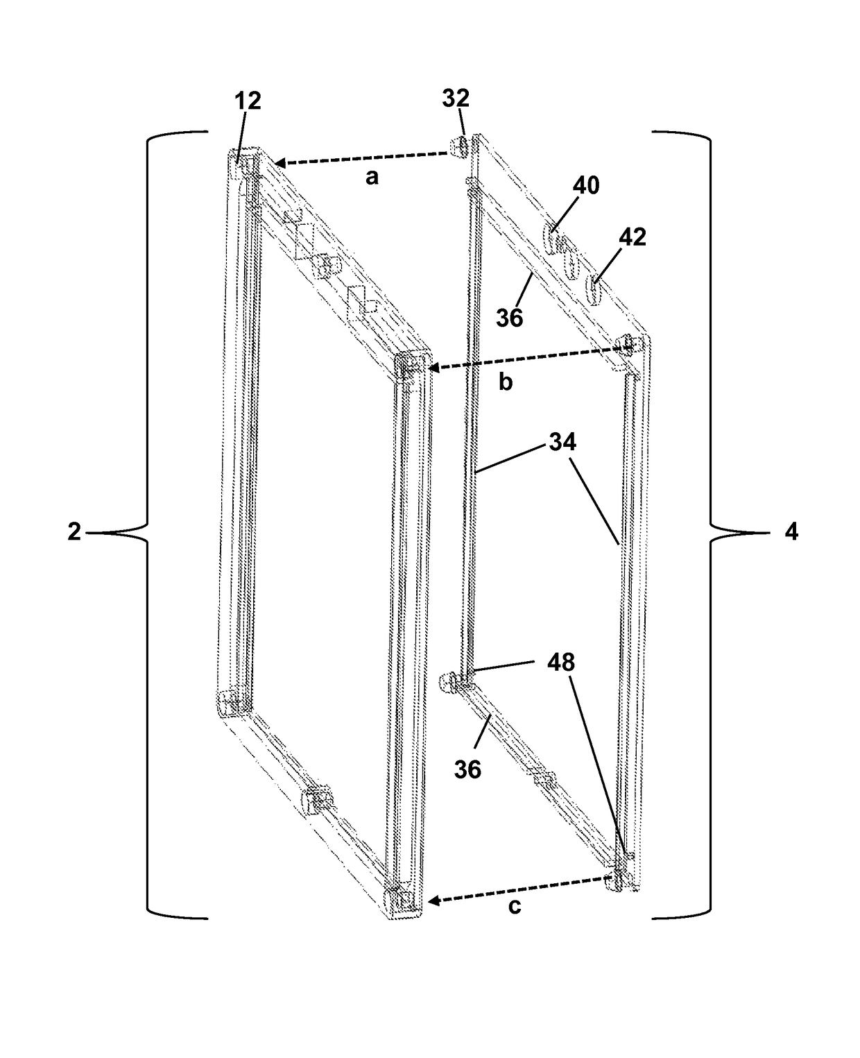
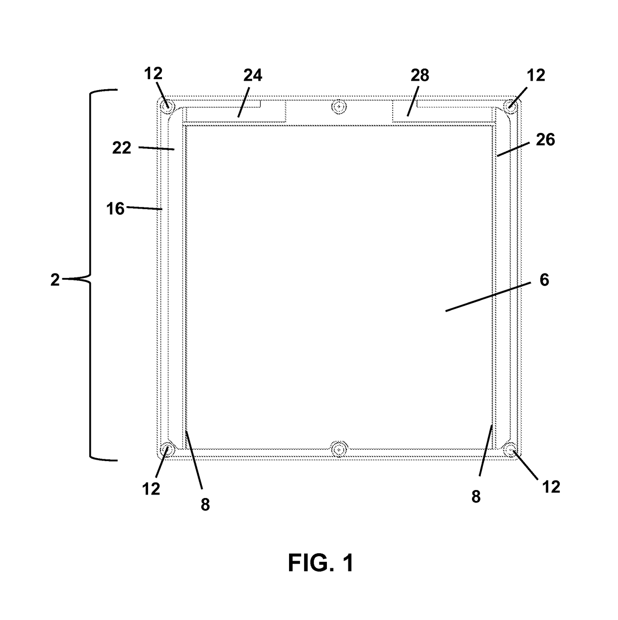
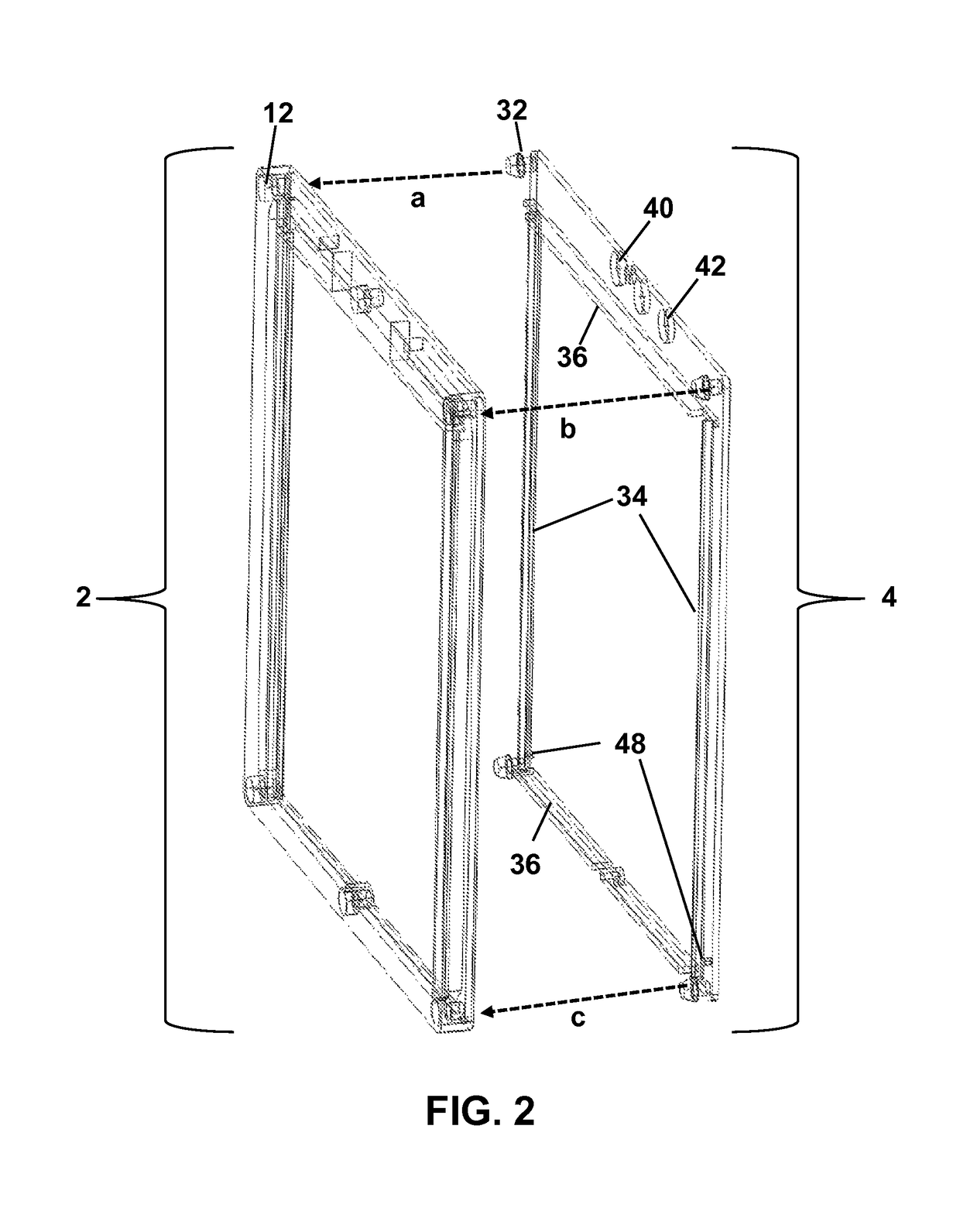

Image

  • Power wafer
  • Power wafer
  • Power wafer

Examples


Embodiment Construction

)

[0084]In the following detailed description, reference is made to the accompanying drawings that form a part hereof, and in which is shown by way of illustration specific examples that can be practiced. It is to be understood that other examples can be utilized and that logical, mechanical, electrical and other changes can be made without departing from the scope of the subject matter of this disclosure. The following detailed description is, therefore, provided to describe exemplary implementations and not to be taken as limiting on the scope of the subject matter described in this disclosure. Certain features from different aspects of the following description can be combined to form yet further aspects of the subject matter discussed below.

[0085]When introducing elements of various embodiments of the present disclosure, the articles “a,”“an,”“the,” and “said” are intended to mean that there are one or more of the elements. The terms “comprising,”“including,” and “having” are int...


PUM

PropertyMeasurementUnit
conductiveaaaaaaaaaa
current-carrying capacityaaaaaaaaaa
insulatingaaaaaaaaaa

Abstract

A power wafer includes an enclosure that houses an energy plate such as a battery, capacitor, super-capacitor or other type of electrical energy storage device. A power wafer uses conductive infusions to make internal electrical connections. In some embodiments, the power wafer has an enclosure formed of a top structure and a bottom structure, which are configured to snap together. The bottom structure has an energy plate void and conductive infusion voids. In some embodiments, the infusions have carbon nanotubes that are magnetically aligned to increase the electrical and thermal conductivity of the infusions. In certain embodiments, the enclosure is configured to hold multiple energy plates in parallel and / or in series to increase the amperage and / or voltage of the power wafer. When the plates are stacked in parallel, an insulating barrier is placed between the plates.

Description

CROSS-REFERENCE TO RELATED APPLICATIONS[0001]This application is related to and claims priority benefits from U.S. Provisional Application No. 62 / 008,223 having a filing date of Jun. 5, 2014, entitled “Battery Wafer”. This application is also related to and claims priority benefits from U.S. Provisional Application No. 62 / 017,212 having a filing date of Jun. 25, 2014, entitled “Battery Wafer Configured to Use Multiple Battery Plates”. This application is a continuation-in-part of U.S. Non-provisional application Ser. No. 14 / 517,766 having a filing date of Oct. 17, 2014, entitled “Battery Management System and Method”. Each of the '223, '212, and '766 applications is hereby incorporated by reference in its entirety.FIELD OF THE INVENTION[0002]The present application relates to electrical energy storage devices and, in particular, to a power wafer. A power wafer includes an enclosure that houses an energy plate, which is a term used to describe a battery, capacitor, super-capacitor or...

Claims


Application Information

Patent Timeline
Patent Type & Authority Patents(United States)
IPC IPC(8): H01M2/24H01G11/78H01M2/26H01M2/30H01M2/36H01M4/66H01M10/04H01G11/76H01M4/75H01M50/529H01M50/54H01M50/55H01M50/553H01M50/609
CPCH01G11/78H01G11/76H01M2/24H01M2/266H01M2/30H01M2/36H01M4/66H01M10/049H01M10/0413H01M10/0436H01M10/0463H01M10/0486H01M4/663H01M4/75H01M2220/20H01M2220/30Y02E60/13Y10T29/42Y10T29/49117Y02E60/10H01M50/529H01M50/54Y02P70/50H01M50/55H01M50/553H01M50/609
Inventor WATERFORD, STEVEZWASKA, THOMAS R.
Owner TRION ENERGY SOLUTIONS CORP
Learn More