
Interconnect structure having large self-aligned vias

a technology of interconnect structure and via, which is applied in the direction of photomechanical treatment originals, instruments, optics, etc., can solve the problems of increasing the difficulty of building metal interconnect structures used to wire transistors together, increasing the difficulty of rc delays, and increasing the height and narrowness of vias, so as to achieve greater lateral packing density, easy filling, and convenient use

Active Publication Date: 2017-05-23
INT BUSINESS MASCH CORP +1
View PDF2 Cites 0 Cited by
  • Summary
  • Abstract
  • Description
  • Claims
  • Application Information

AI Technical Summary

Benefits of technology

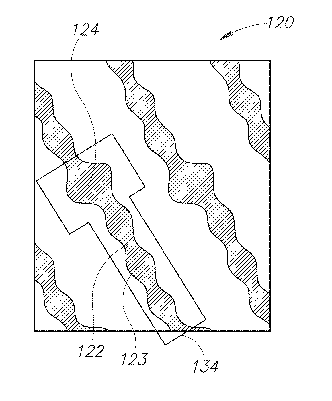
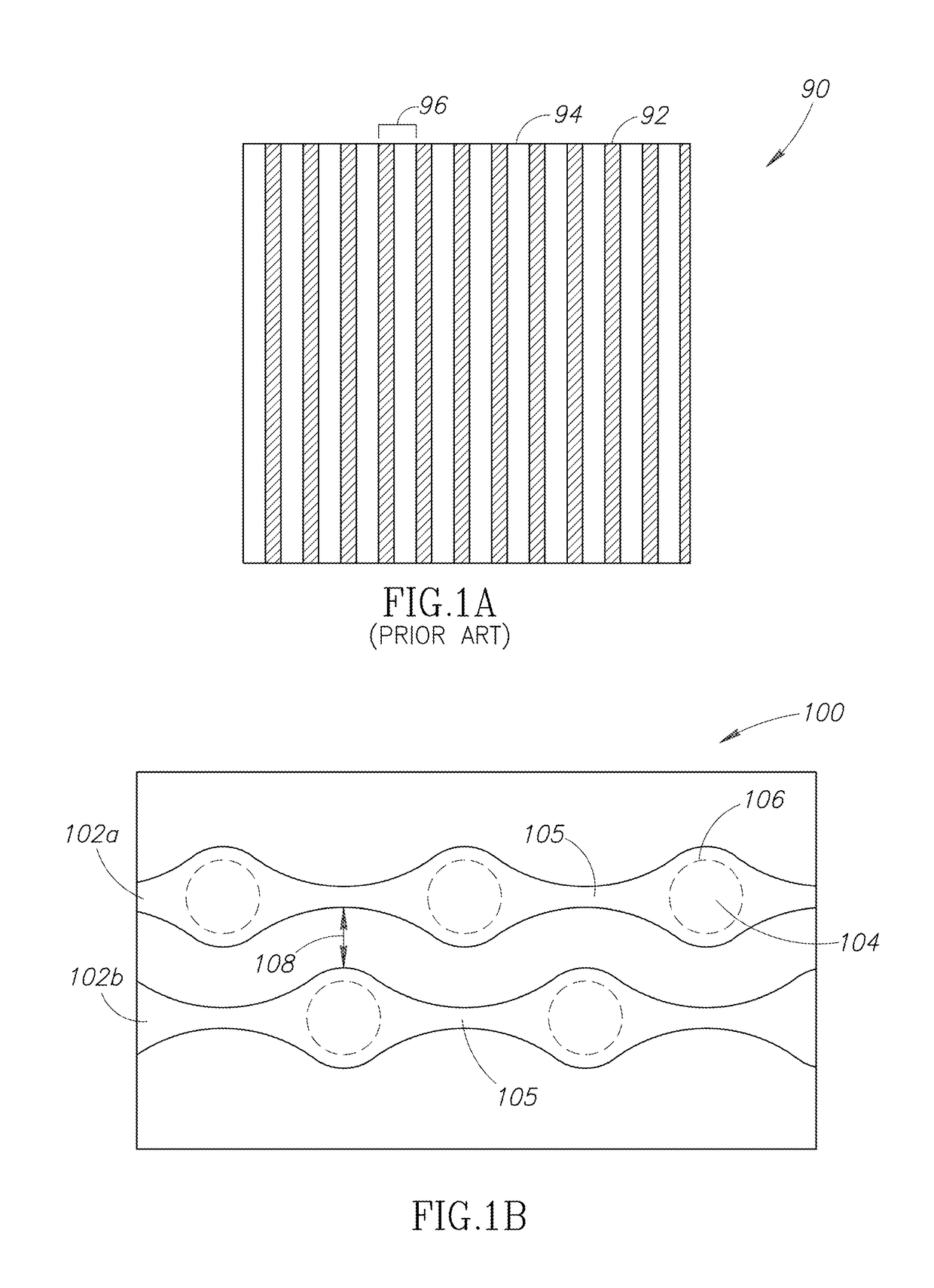
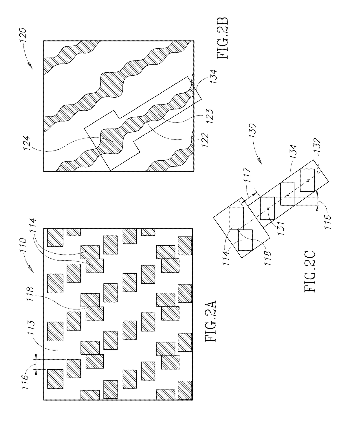
[0006]An interconnect structure having wavy metal lines allows via footprints to exceed the nominal width of metal line portions connecting them. In one embodiment, the resulting metal line profile shape resembles a bicycle chain. In another embodiment, the metal line resembles a linear series of T-shaped unit cells, in which the width of the metal line alternates between a narrow value, an intermediate value, and a wide value. The wide value corresponds to a large via landing pad for vias forming an electrical connection to the next highest metal layer. To achieve greater lateral packing density, adjacent wavy metal lines can be staggered so that the via landing pads on one metal line are next to the narrow metal connecting portions of neighboring metal lines. By lifting the shrink constraint for vias, thereby allowing the via footprint to exceed the minimum size of the metal line width, a path is cleared for further process generations to continue shrinking metal lines to dimensions below 10 nm.
[0007]A wavy line interconnect structure can be formed using a dual damascene process in which vias are self-aligned without the need for a dedicated lithography mask. Instead, metal line trenches are lined with a sacrificial layer that completely fills the narrow spaces while under-filling the wide spaces that correspond to via locations. The sacrificial layer thus acts as a via hard mask, allowing etching of the underlying thick dielectric block, while protecting narrow features of the trenches that correspond to the metal line interconnects. The resulting vias have an aspect ratio that is relatively easy to fill, while the larger footprint provides low via resistance.

Problems solved by technology

As integrated circuit technology advances, building metal interconnect structures that are used to wire transistors together becomes more and more challenging.
However, smaller vias incur higher via resistance, causing RC delays to worsen.
In addition, smaller via footprints cause the via aspect ratio, i.e., the ratio of height to width, to increase, making the vias taller and narrower, and therefore more difficult to fill with metal.
Incomplete via fill in turn degrades reliability by causing open circuit failures, for example.

Method used


Image

  • Interconnect structure having large self-aligned vias
  • Interconnect structure having large self-aligned vias
  • Interconnect structure having large self-aligned vias

Examples


Embodiment Construction

[0028]In the following description, certain specific details are set forth in order to provide a thorough understanding of various aspects of the disclosed subject matter. However, the disclosed subject matter may be practiced without these specific details. In some instances, well-known structures and methods of semiconductor processing comprising embodiments of the subject matter disclosed herein have not been described in detail to avoid obscuring the descriptions of other aspects of the present disclosure.

[0029]Unless the context requires otherwise, throughout the specification and claims that follow, the word “comprise” and variations thereof, such as “comprises” and “comprising” are to be construed in an open, inclusive sense, that is, as “including, but not limited to.”

[0030]Reference throughout the specification to “one embodiment” or “an embodiment” means that a particular feature, structure, or characteristic described in connection with the embodiment is included in at le...


PUM

PropertyMeasurementUnit
widthsaaaaaaaaaa
widthsaaaaaaaaaa
distanceaaaaaaaaaa

Abstract

A wavy line interconnect structure that accommodates small metal lines and large vias is disclosed. A lithography mask design used to pattern metal line trenches uses optical proximity correction (OPC) techniques to approximate wavy lines using rectangular opaque features. The large vias can be formed using a self-aligned dual damascene process without the need for a separate via lithography mask. Instead, a sacrificial layer allows etching of an underlying thick dielectric block, while protecting narrow features of the trenches that correspond to the metal line interconnects. The resulting vias have an aspect ratio that is relatively easy to fill, while the larger via footprint provides low via resistance. By lifting the shrink constraint for vias, thereby allowing the via footprint to exceed the minimum size of the metal line width, a path is cleared for further process generations to continue shrinking metal lines to dimensions below 10 nm.

Description

BACKGROUND[0001]Technical Field[0002]The present disclosure generally relates to high speed integrated circuits, and in particular, to the fabrication of interconnect structures using a self-aligned dual damascene process.[0003]Description of the Related Art[0004]As integrated circuit technology advances, building metal interconnect structures that are used to wire transistors together becomes more and more challenging. Metal lines can assume a variety of different shapes, from straight wires to cells made up of intertwined C-shapes. Regardless of their shapes, design rules for metal lines are typically based on scaling a pitch dimension that assumes a regular pattern of equal line widths and spacings between the metal lines at each metal layer. Metal line widths are generally expected to shrink with every new process generation to further improve integrated circuit performance.[0005]Depending on the type of process integration scheme used, vias connecting stacked metal lines vertic...

Claims


Application Information

Patent Timeline
Patent Type & Authority Patents(United States)
IPC IPC(8): G03F1/36H01L21/027H01L21/311H01L21/768H01L23/522H01L23/528
CPCG03F1/36H01L21/0274H01L21/31144H01L21/76808H01L21/76816H01L23/528H01L23/5226H01L2924/0002H01L2924/00G03F1/00
Inventor ZHANG, JOHN H.CLEVENGER, LAWRENCE A.RADENS, CARLXU, YIHENGWISE, RICHARD STEPHENSPOONER, TERRYSAULNIER, NICOLE A.
Owner INT BUSINESS MASCH CORP
Learn More