Electrically conductive balloon catheter

a technology catheter, which is applied in the field of electric conductive balloon catheter, can solve the problems of long time-consuming and laborious, difficult, if not impossible, to assess the spatial dynamics between articular surfaces, and the difficulty of real-time measurement of the inner surface of the bones, etc., and achieves the effects of effective visualizing internal structures, simple, cost-effective and reliable sensors

Active Publication Date: 2017-06-27
SANOVAS
View PDF31 Cites 0 Cited by
  • Summary
  • Abstract
  • Description
  • Claims
  • Application Information

AI Technical Summary

Benefits of technology

[0015]It is yet another object of the present invention to provide a balloon catheter system and method for effectively visualizing internal structures in very small cavities (e.g., intravascular measurement).
[0016]It is a further object of the present invention to provide a balloon catheter system and method for effectively visualizing and measuring the spaces between and / or within internal structures in very small cavities (e.g., Intra-articular measurement; Intra-cavital measurement).
[0017]It is still another object of the present invention to provide a balloon catheter system and method for visualizing internal structures that provides a simple, cost-effective and reliable sensor(s) that generate a signal having a signal format that is robust and can be processed in a cost-effective manner.
[0020]It is understood that precise impedance measurement(s) are widely available and cost-effective. For example, to achieve high measurement accuracy with relatively low product cost, the signal processing technique of Discrete Fourier Transform (DFT) may be used with error correction to the impedance measurements. Software can effectively be used to control signal processing and error correction.

Problems solved by technology

While these methods can be very effective at visualizing internal structures, the cost associated with the purchase and use of these machines is relatively high.
In the field of orthopedics it is often difficult, if not impossible, to assess the spatial dynamics between articular surfaces; especially as the articular surfaces translate in opposition to one another throughout their ranges of motion.
The Orthopedic and Trauma science has long struggled to visualize and measure the inner surfaces of bones in real time.
The inability to map bone anatomy has hindered surgeon's ability to appropriately size and implant arthroplasty implants (e.g.—Hip Replacement—Femoral and Acetabular Implants).
It has also hindered surgeons ability to assess the displacement of fractures and to appropriately size and implant fracture management systems (e.g.—Tibial Rodding and Plating systems).
This is cumbersome, difficult to manipulate and not practical for relative small cavities (e.g., intravascular measurement).
13-15), Murphy is limited to disclosing “conductor bands.” This will not provide a 3-dimensional view of the interior of a cavity, but rather, will only provide a cross-sectional circumference of a cavity.

Method used


Image

  • Electrically conductive balloon catheter
  • Electrically conductive balloon catheter
  • Electrically conductive balloon catheter

Examples


Embodiment Construction

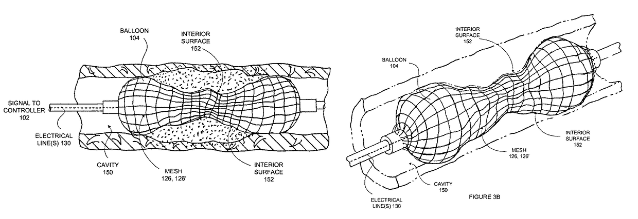
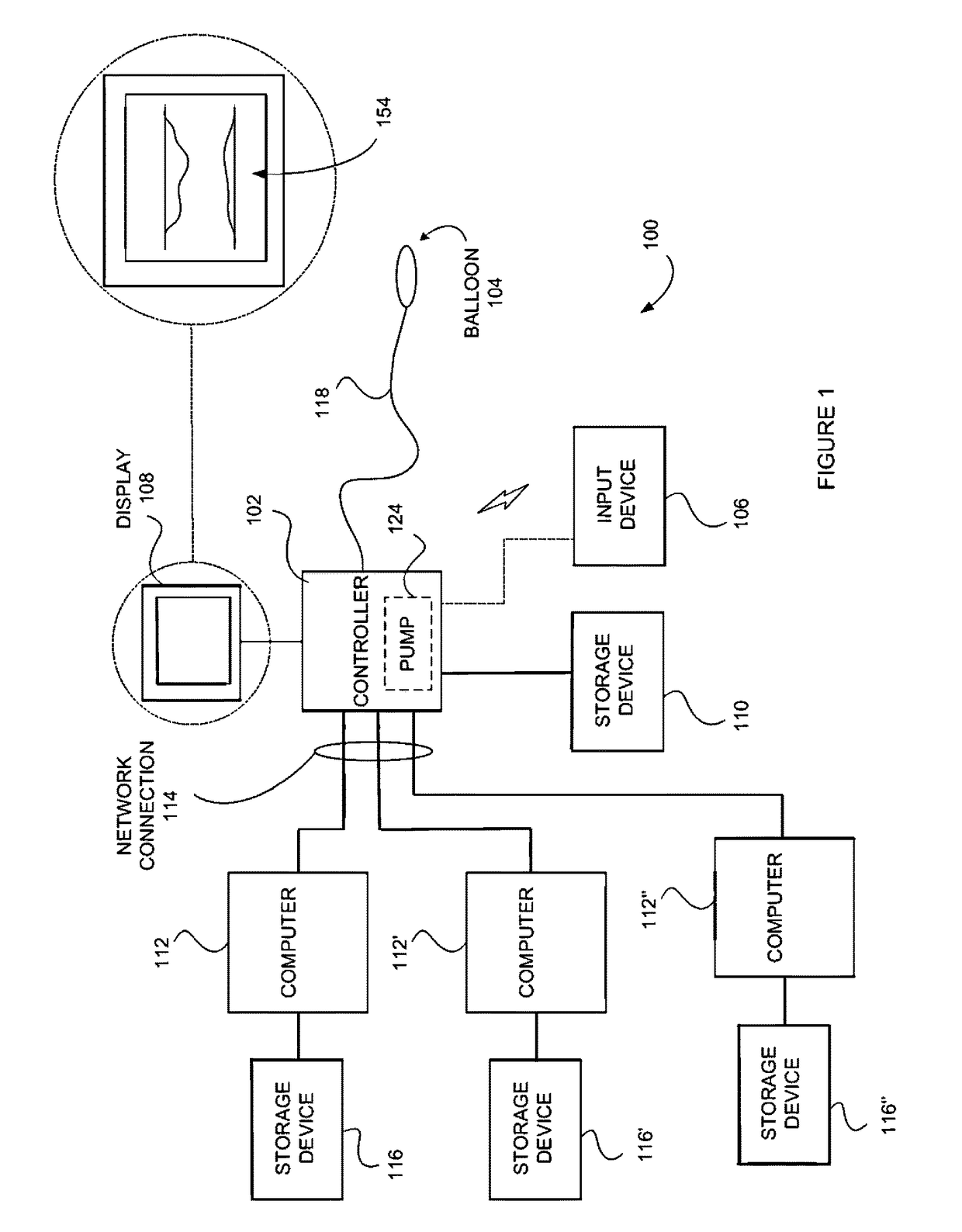
[0046]Referring now to the drawings, FIG. 1 is a block diagram of an advantageous embodiment of a system 100 for generating a three dimensional image of an interior of a body cavity 150 (FIGS. 3A and 3B).

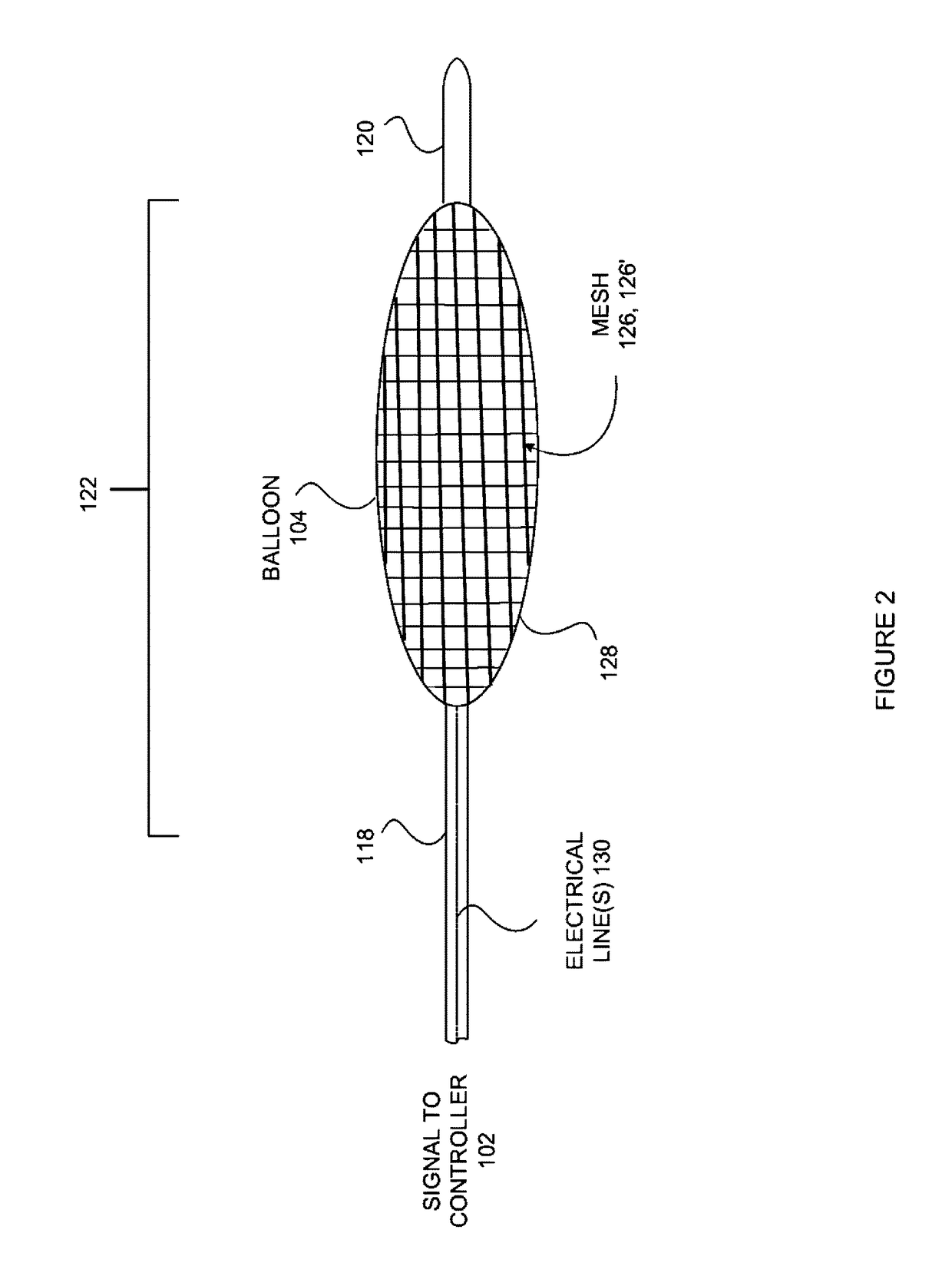
[0047]The system 100 includes a controller 102, which may comprise any type of controller known in the art for controlling the inflating and deflating of a balloon 1104 attached thereto by means of a catheter 118 that includes electrical lines 130 to communicate with the controller 102. The controller 102 is coupled to an input device(s) 106 that may comprise virtually any type of interface including, for example but not limited to, a keyboard, a mouse, a touch screen or touch pad, a voice-activated control input device, etc. It is understood that input device 106 may be either wired or wireless, which is illustrated by the use of a dashed line and wireless transmission signal indication in FIG. 1. It is still further contemplated that the input device may comprise a mobile wireless...


PUM

PropertyMeasurementUnit
lengthaaaaaaaaaa
lengthaaaaaaaaaa
lengthsaaaaaaaaaa

Abstract

A balloon catheter having a mesh affixed thereto. The mesh is formed having members extending longitudinally and circumferentially about the balloon into columns and rows respectively. Each member of the mesh has a resistance or impedance that changes as the member is deformed such that, when the member comprises a length (L) a measured resistance or impedance will be different than when the member comprise a length (L1) where L1 is greater than L.

Description

CROSS-REFERENCE TO RELATED APPLICATIONS[0001]The present application claims the benefit under 35 U.S.C. §119 (e) of the U.S. Provisional Patent Application Ser. No. 61 / 472,950 filed on Apr. 7, 2011, which is incorporated herein by reference.FIELD OF THE INVENTION[0002]The invention relates to a system and method for visualizing and measuring the interior of a body cavity and more specifically, relates to visualization and measurement of a body cavity with a balloon catheter by measuring the electrical characteristics of an inflated balloon in the body cavity.BACKGROUND OF THE INVENTION[0003]Balloon catheters are used for various medical procedures. For example, it is known to insert a balloon catheter into a passageway for dilation of the passageway such as is used in interventional bronchoscopy for the treatment of lung cancer and oft times, the resultant airway obstruction(s) that occur. Accordingly, balloon catheters have been routinely used with various endoscopes and with flexi...

Claims


Application Information

Patent Timeline
Patent Type & Authority Patents(United States)
IPC IPC(8): A61B5/107A61B5/00
CPCA61B5/6853A61B5/1076A61B2562/046F04C2270/041Y10T29/49124
Inventor GUNDAY, ERHAN H.GERRANS, LAWRENCE J.CHU, LON
Owner SANOVAS
Why Eureka
Try Eureka