Methods and devices for drying hydrocarbon containing gas

a technology of hydrocarbon and gas, which is applied in the direction of gaseous fuel, liquefaction, lighting and heating apparatus, etc., can solve the problems of low efficiency, generally not used in conventional cooling equipment, and vortex tubes

Inactive Publication Date: 2017-06-27
LEED FABTION SERVICES
View PDF32 Cites 1 Cited by
  • Summary
  • Abstract
  • Description
  • Claims
  • Application Information

AI Technical Summary

Benefits of technology

[0005]Provided herein are processes and devices for processing a hydrocarbon containing gas. In particular, the systems decrease the temperature of the hydrocarbon containing gas such that hydrocarbon vapors condense and are removed from the gas. The advantages of the instant disclosure are that the systems do not require significant external energy and, in certain embodiments, are self-sufficient and self-maintaining. In this manner, valuable end products are obtained, such as natural gas liquids (NGLs) condensed from a hydrocarbon containing gas whose value may otherwise not be fully captured. Furthermore, hydrocarbon containing gas is dried and may also be collected or, as desired, more reliably combusted compared to wet gases containing mixture of hydrocarbons, including relatively heavy hydrocarbons that are not removed via the instant condensation process. These functional benefits are all provided without any complex equipment, materials, refrigerants or additional energy requirements. Accordingly, the payoff timeframe for the systems and methods provided herein is rapid and reliable.
[0010]Any of the systems and processes provided herein utilize a special configuration for compressing air, such as by mechanically coupling a boundary layer disk turbine (BLDT) to a compressor pump, directing a flow of a pressurized drive fluid over the BLDT to mechanically power the compressor pump, and compressing air with the mechanically powered compressor pump. In this manner, an external energy source is not required to power the compressor, and the NGL recovery can occur without external power consumption.
[0020]Provided herein are various industrial processes, and systems that incorporate those industrial processes, wherein one component of the process relates to a flow of a drive fluid that is an integral part of the industrial process. Flow of the drive fluid is used to provide power or control to other components of the process. In this manner, the flowing fluid itself can significantly reduce the requirement for an external power source to control or drive the process, including to drive specific components thereof. In an aspect, the drive fluid may be the gas phase portion of a hydrocarbon recovery or storage unit, such as a vapor gas that flashes from the liquid phase. The vapor gas may be under pressure, and released to a conduit connected to a boundary layer disk turbine (BLDT), so that the pressurized vapor gas flows over the BLDT under a pressure gradient, thereby mechanically driving the BLDT. The BLDT can then be connected and employed in various configurations to advantageously drive other components depending on the specific industrial process. For example, pneumatics can be powered by connecting the BLDT to a compressor pump to compress a compressible fluid, such as air, wherein the compressed fluid is controllably used to power pneumatics as desired. Alternatively, the compressor pump may compress a hydrocarbon vapor gas to a desired pressure, such as to a desired sales or pipeline pressure. Alternatively, the compressor pump may compress air to a desired compression pressure. Alternatively, the BLDT can be used to both compress hydrocarbon vapor gas and / or to compress another fluid, such as air, to run a pneumatic device within the industrial process and / or for cooling a hydrocarbon containing gas to remove condensable heavy hydrocarbons from the gas.
[0047]One embodiment of the present invention is directed to a self-powered compressor. “Self-powered” refers to a compressor capable of reliably running for extended periods of time without a source of electrical or chemical energy, and instead relies on fluid flow inherent in the industrial process itself to mechanically drive a compressor. In an aspect, the self-powered compressor comprises a pressure vessel containing a source of pressurized drive fluid, and a closed-loop circuit fluidically connected to a boundary layer disk turbine (BLDT) and the pressure vessel. The closed-loop circuit provides flow of the pressurized drive fluid to the BLDT under a pressure differential without loss or bleeding of the drive fluid. A compressor pump is mechanically connected to the BLDT, wherein flow of the pressurized drive fluid mechanically powers the compressor via the BLDT motion. “Pressurized fluid” refers to the fluid being at a sufficiently high pressure that it is capable of flowing over the BLDT, thereby turning the BLDT. The BLDT is, in turn, mechanically coupled directly or indirectly, to the compressor pump such that motion of the BLDT results in compressor pump compressing a compressible fluid.

Problems solved by technology

Vortex tubes, however, are generally not used in conventional cooling equipment because they are of relatively low efficiency.

Method used


Image

  • Methods and devices for drying hydrocarbon containing gas
  • Methods and devices for drying hydrocarbon containing gas
  • Methods and devices for drying hydrocarbon containing gas

Examples


example 1

Hydrocarbon-Containing Gas

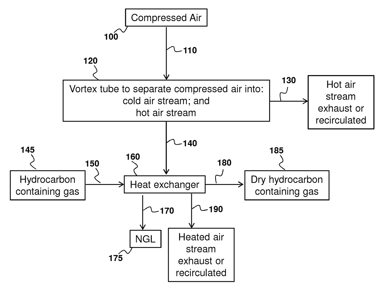
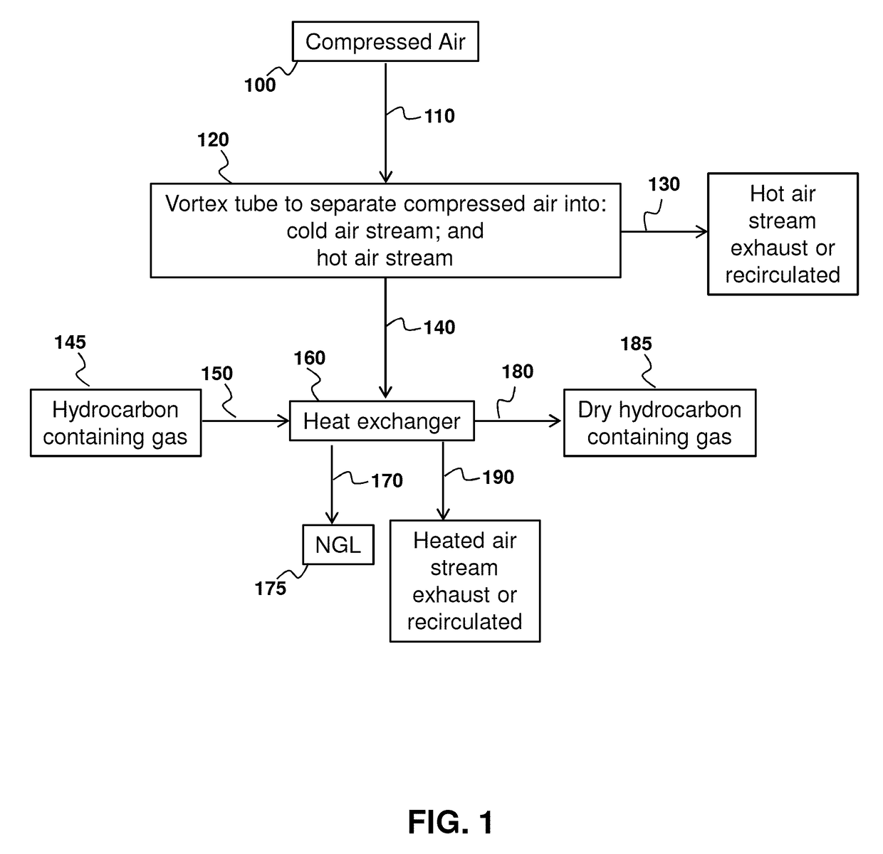
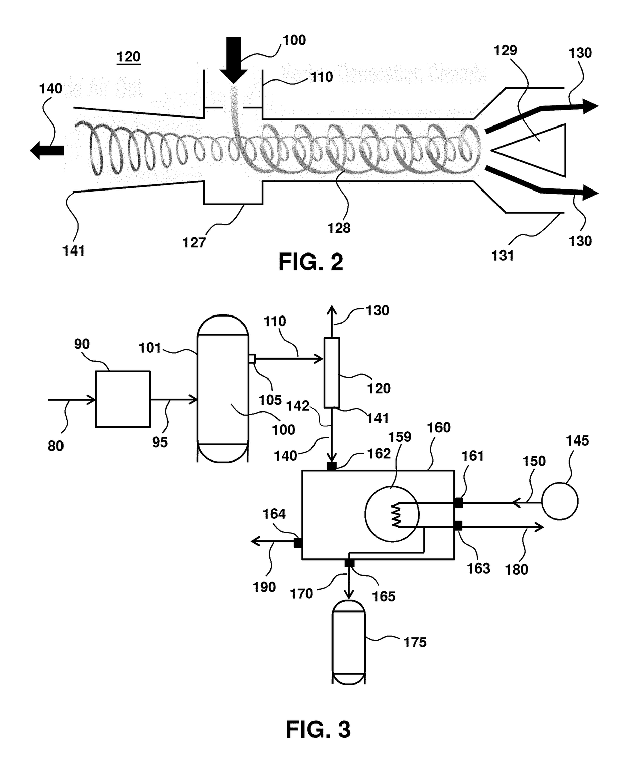
[0079]One example of a process for drying a hydrocarbon-containing gas is provided by the process flow chart of FIG. 1. Compressed air 100 is introduced 110 to a vortex tube 120. The compressed air 100 may be directly from a compressor or indirectly from a compressor such as via storage tank. The vortex tube 120 separates the compressed air into a hot air stream 130 and a cold air stream 140. The cold air stream 140 is introduced to a heat exchanger 160. Hydrocarbon containing gas (e.g., wet hydrocarbon containing gas) 150, such as from a source 145 is introduced to the heat exchanger 160. Functionally, the cold air stream 140 decreases the temperature of the hydrocarbon containing gas in the heat exchanger, thereby condensing natural gas vapors in the hydrocarbon containing gas to liquid hydrocarbons (referred herein as natural gas liquids or NGL) 170 that are collected 175 from the heat exchanger. Hydrocarbon containing gas from which NGLs have been conde...

example 2

red Compressor to Compress Fluids

[0085]FIG. 4 summarizes certain steps of a process for compressing a fluid, such as air for use in the process and devices described in Example 1. Briefly, pressurized drive fluid drives a disk turbine (e.g., BLDT) 500 and is looped back into the fluid flow at an appropriate location in the process 510. For example, FIG. 5 illustrates the outlet flow conduit 235 from the BLDT connected back to a line from the pressure vessel 210 or another line 211, such as a sales line or a hydrocarbon-containing gas line that is introduced to heat exchanger 160 of FIGS. 1 and 3. Because the fluid remains in the industrial process and is not, for example, vented to atmosphere, the connection is referred to as a “closed-loop”200. The BLDT drives a compressor pump 520 through any coupling means, direct or indirect. The compressor pump compresses a compressible fluid 530, such as air to provide compressed air 100. Depending on the desired application 550, the compresse...


PUM

PropertyMeasurementUnit
pressureaaaaaaaaaa
temperatureaaaaaaaaaa

Abstract

Processes and devices for recovering natural gas liquid from a hydrocarbon containing gas are provided by introduction of compressed air to a vortex tube. The vortex tube generates a cold air stream that is introduced into a heat exchanger. A hydrocarbon containing gas of higher temperature than the cold air stream is introduced into the heat exchanger, so that the cold air stream in the heat exchanger cools the hydrocarbon containing gas to condense natural gas vapors in the hydrocarbon containing gas to liquid hydrocarbons. In this manner, liquid hydrocarbons and dry hydrocarbon containing gas are obtained.

Description

CROSS-REFERENCE TO RELATED APPLICATIONS[0001]This application claims the benefit of U.S. Provisional Application No. 61 / 782,214, filed Mar. 14, 2013, which is hereby incorporated by reference in its entirety to the extent not inconsistent herewith.BACKGROUND OF THE INVENTION[0002]Provided are devices and methods for condensing hydrocarbon vapors from a hydrocarbon containing gas using energy inherent to the industrial process. In this manner, the process is extremely energy efficient with attendant increase in revenue to the producer without sacrifice in process reliability or efficiency.[0003]Vortex tubes or Ranque-Hilsch vortex tubes are known in the art and are used to provide spot cooling. Vortex tubes, however, are generally not used in conventional cooling equipment because they are of relatively low efficiency. In addition, for substantial cooling, highly compressed air is required. Vortex tubes have certain advantages if the above concerns can be addressed as cooling via vor...

Claims


Application Information

Patent Timeline
Patent Type & Authority Patents(United States)
IPC IPC(8): F25J3/00F25J3/06F25B9/04C10L3/10
CPCF25J3/061C10L3/101F25B9/04F25J3/064F25J3/0635F25J3/0645F25J2240/90F25J2220/64F25J2230/20
Inventor BEELER, CASEY L.
Owner LEED FABTION SERVICES
Why Eureka
Try Eureka