
Strainer/filter unit for an aspirating filtration system and method thereof

a filter unit and filter unit technology, applied in the direction of filtration separation, teeth capping, separation process, etc., can solve the problems of exposing dental professionals and patients to amalgam, unable to effectively filter small amalgam and other solid, liquid or gaseous particles, etc., to achieve the effect of convenient disposal and cost saving

Active Publication Date: 2017-07-04
COHEN HOWARD
View PDF36 Cites 10 Cited by
  • Summary
  • Abstract
  • Description
  • Claims
  • Application Information

AI Technical Summary

Benefits of technology

The present invention is a strainer / filter unit that collects solid, liquid, and gaseous matters at the source for use in a vacuum-operated aspirating system. The strainer / filter unit prevents the back-flow of solids, liquids, and gases and eliminates the need for dental unit traps, chairside traps, cuspidor traps, and traps used in the pipelines of the vacuum / suction system and pump. It is an efficient and effective solution for collecting debris during dental procedures.

Problems solved by technology

When such fluids and gases are withdrawn from the patient's mouth (as by a vacuum powered saliva ejector or a high-volume aspirator / evacuator (HVE)), this solid matter can cause difficulties for the dentist and for the patient especially when the patient is anesthetized.
Additionally, the solid matter can clog the vacuum / suction system and water waste line so as to cause it to malfunction.
Another such difficulty is that the solid, liquid and gaseous matters can be incorporated in an aerosol created during a dental procedure and the build up of the solid matter can occur on the inner surfaces of the vacuum / suction and dental unit lines and suction and water waste lines, thereby forming an area for the growth of bio-film that in turn promotes the growth of bacteria.
However, such trap cannot effectively filter small amalgams and other solid, liquid or gaseous particles and unnecessarily expose dental professional and patients to amalgam (and its mercury vapors and methyl mercury) in the operatory.
Existing amalgam separators typically require professional installation and are costly to install and maintain.
If the U.S. is to ban its use, it is estimated to cost the public's dental expenses of $8.2 billion during the first year.
Laws are being enacted mandating the use of amalgam separators based upon faulty science and such laws are a burden to those dentists who perform procedures involving amalgam as well as being misleading to environmentalists, the EPA and waste water and sludge treatment plants.
Other investigators have noted that clinical evaluation of existing amalgam separators would be difficult to perform and an article by the American Dental Association (ADA) dated Aug. 5, 2005, entitled “Summary of Recent Study of Dental Amalgam in Waste Water” states that “measuring the exact amount of amalgam waste being generated and discharged from a dental office is a very difficult task.
The discharge of amalgam waste into sewerage systems is complicated by the fact that this waste is generated on an intermittent basis with huge day-to-day and even minute-to-minute variations.
Methods such as sampling from drain or sewer lines, or even collecting total waste over several days show huge variations that are difficult to extrapolate into total waste generated over a year.
For these reasons, sampling dental office wastewater discharge does not provide either an accurate or reliable estimate of discharge.”
In such a situation the use of disinfectants such as sodium hypochlorite will change the accumulated amalgam particles into methyl mercury which is considered toxic and the most hazardous form of amalgam waste.
Further, it is important to note that when the vacuum valves, air compressor for tools and water lines are shut off after a procedure for a patient, microbial contamination of the dental unit and water lines can occur due to the “suck back” phenomenon, which may be partially embedded in an existing biofilm.
This “suck back” phenomenon increases the likelihood of dental acquired infections.
All existing amalgam separators must be clinically considered to be inadequate in meeting the ISO Standard 11143 as they are not removing 95% of the amalgam particles generated.
Another problem exists with prior art amalgam separators in that it is necessary to maintain a pH in the range of 5 to 10 within the dental units and pipelines of the suction system.
Although bleach is typically used in dental procedures (to sterilize and disinfect root canal or to etch the tooth for bonding or tooth whitening or bleaching), bleach cannot be used with existing amalgam separators because it would adversely affect the pH level in the pipelines of the suction system.
A pH below or above the 5 to 10 range may adversely affect the amalgam particles attached to the biofilm or amalgam particles resulting from a procedure involving amalgam so as to possibly cause the release of mercury vapors or result in the production of methyl mercury that is toxic and considered the most hazardous particle form from amalgam.
First, existing strainer / filter units within the dental unit and suction lines of saliva ejectors and HVE aspirators are difficult, if not impossible, to sterilize.
The Food and Drug Administration (FDA) regulations in the United States do not require the strainer / filter units to be sterile as well as the saliva ejectors and aspirators and they need only be cleaned, which in itself is labor intensive and not cost effective.
Even if a particular dentist is motivated to sterilize a strainer / filter unit and aspirator before connecting them to the dental unit and vacuum systems, existing strainer / filter units and aspirators can neither be easily emptied nor cleaned and sterilized.
Hence, the strainer / filter unit and aspirator / HVE or saliva ejector holders used during a dental procedure on a patient may be unsterile at the beginning of the procedure.
This poses a danger that substances and debris from dental procedures performed earlier in the day may cross-contaminate (as by back flowing solid or fluid as well as airborne substances into the patients' mouth or due to the suck-back phenomenon) who is undergoing a dental procedure later on that day.
Therefore, if a dentist is motivated to use a sterile strainer / filter unit for each patient, the dentist must make a considerable investment in strainer / filter units and must incur increased operating expenses to clean and sterilize them.
Secondly, existing strainer / filter units are not versatile (the saliva ejector shown in U.S. Pat. No. 3,890,712 by Lopez is an example of such a non-versatile device).
Prior art strainer / filter units are designed to work only with a particular type of saliva ejector or aspirator and cannot easily be used with other types of similar devices.
Thirdly, existing sterile strainer / filter units are relatively expensive.
Fourthly, the cost and time associated with emptying and replacing dental unit traps can be high.
Lastly, existing strainer / filter units do not properly filter all amalgam particles (whether in solid, liquid or vapor form) and keep the amalgam from regurgitating.
Some amalgam particles in solid, liquid or vapor form never reach the conventional amalgam separators.
Additionally, this prior art device does not prevent regurgitation or back flow of the amalgam as well as other solids, fluids and airborne gaseous substances collected in the strainer / filter unit.

Method used


Image

  • Strainer/filter unit for an aspirating filtration system and method thereof
  • Strainer/filter unit for an aspirating filtration system and method thereof
  • Strainer/filter unit for an aspirating filtration system and method thereof

Examples


Embodiment Construction

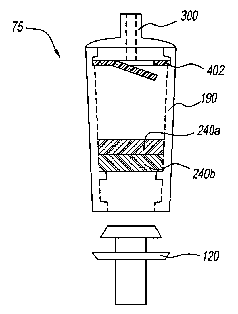
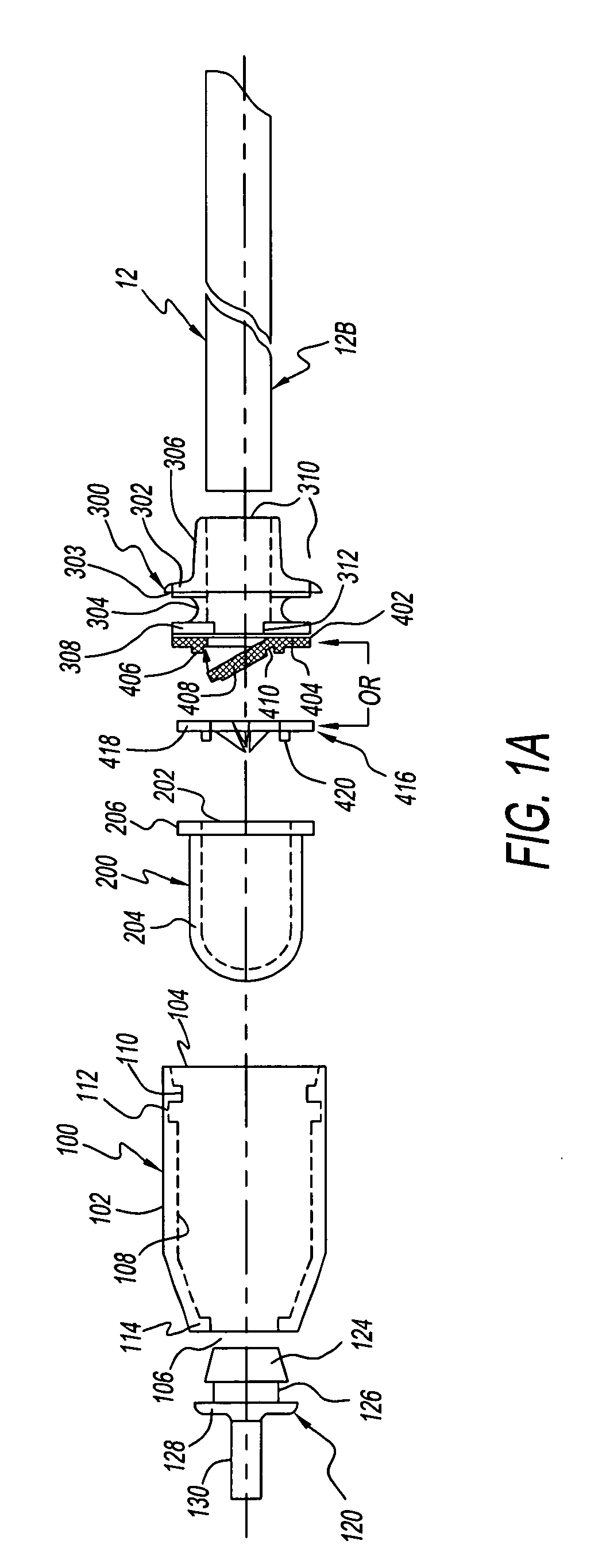
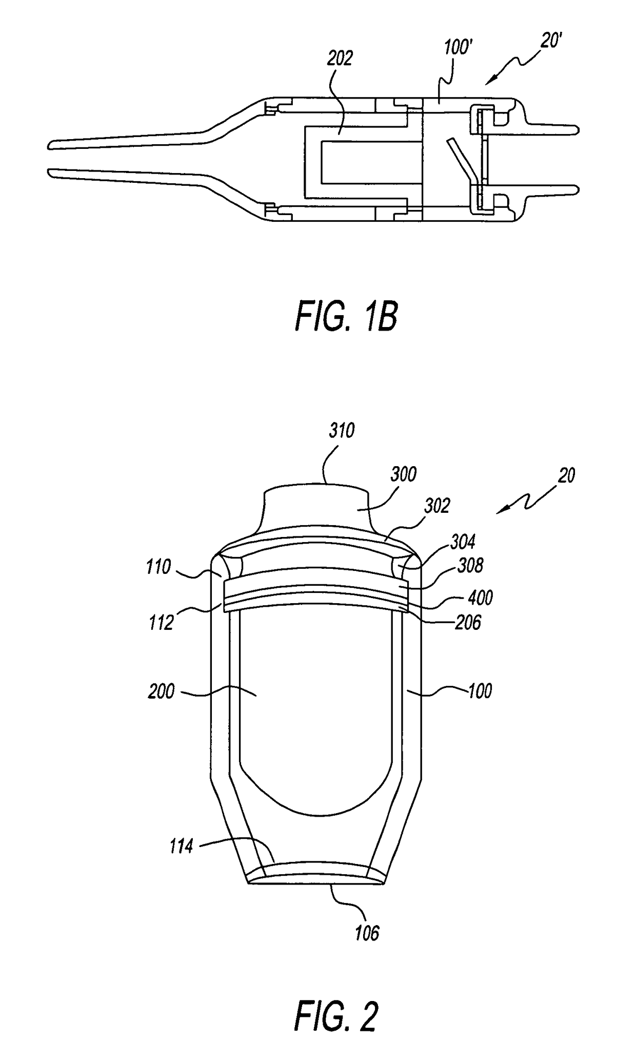
[0062]With reference to the drawings wherein the same reference number illustrates the same element throughout, FIGS. 1A and 2 show the strainer / filter unit 20 of the present invention, which include a housing 100, a filter 200 that fits in the housing 100 and a cap 300 that encloses the filter 200 in the housing 100.

[0063]As shown in FIG. 1A, housing 100 has a generally tubular body 102 with an inlet end 104 and an outlet end 106. The tubular body 102 is tapered at the outlet end 106. The inner wall 108 of the body 102 at the inlet end 104 tapers to a smaller diameter to form a radially extending lip 110. Abutting the lip 110 is a circular groove 112 with a diameter larger than the inner diameter of the lip 100. The inner wall 108 of the body 102 at the outlet end 106 has a radially extending rib 114 with a diameter smaller than the inner wall 108. The outlet end 106 is adapted to engage the valve of a saliva aspirator device 15 (not shown) or an outlet adaptor 120 before connectin...


PUM

PropertyMeasurementUnit
pore sizeaaaaaaaaaa
pore sizeaaaaaaaaaa
pore sizeaaaaaaaaaa

Abstract

A strainer / filter unit for effectively collecting solid, liquid or gaseous substances at the source and the method of using the strainer / filter unit. The strainer / filter unit includes a housing, a one-way valve at one end of the housing, and a filter having a certain depth and thickness within the housing. The filter is formed from a plurality of layers of material with pores such that pores of one layer partially overlap pores of subsequent adjacent layers. Matters entering the strainer / filter unit are collected in the filter while travelling through filter via a tortuous path.

Description

FIELD OF THE INVENTION[0001]The invention relates to an apparatus that collects solid waste at the source and the method thereof. In particular, a strainer / filter unit having an anti-retraction valve and a filter with an appropriate depth and thickness such that solid matters are collected while travelling through a tortuous path and for use in connection with a vacuum-operated type aspirating system that aspirates liquids, solids and gases, and prevents the back-flow of liquids, solids and gases. The present invention is particularly useful in the dental field.BACKGROUND OF THE INVENTION[0002]Dental procedures can cause solid matter (e.g. bone chips, tooth particles, tissue fragments, pieces of amalgam, mercury, other toxic or hazardous chemicals, composite residual, fragments of porcelain restoration, zirconium, aluminum oxide, and cleaning paste that contains silica, etc.) to enter fluids (e.g. saliva, blood, and cooling water) that are present in the patients' mouth. The solid m...

Claims


Application Information

Patent Timeline
Patent Type & Authority Patents(United States)
IPC IPC(8): A61C17/06A61C17/14A61M1/00
CPCA61C17/046A61M1/0056A61C17/043A61C17/065A61C17/08A61M1/79
Inventor COHEN, HOWARD
Owner COHEN HOWARD
Learn More