Semiconductor device

a technology of semiconductors and devices, applied in the direction of semiconductor devices, electrical equipment, transistors, etc., to achieve the effects of reducing the resistance of drift regions, improving rsp, and increasing breakdown voltag

Active Publication Date: 2017-07-04
KEY FOUNDRY CO LTD
View PDF18 Cites 10 Cited by
  • Summary
  • Abstract
  • Description
  • Claims
  • Application Information

AI Technical Summary

Benefits of technology

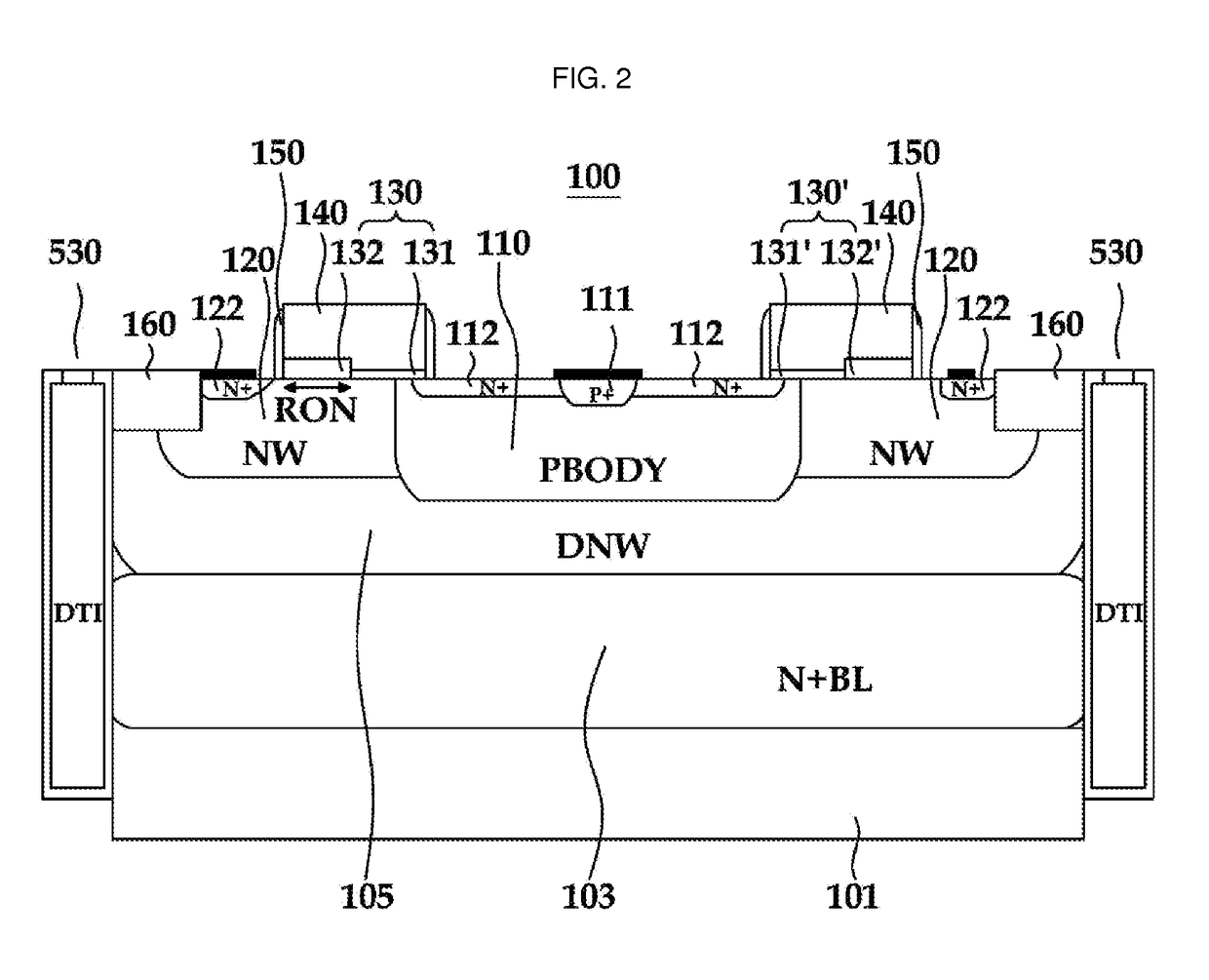
[0010]Thus, an object of the examples is to provide a high voltage or an electric semiconductor device with low Ron and Rsp to reduce power loss, as discussed further above.
[0029]A high voltage semiconductor device of the examples discussed as above has the following effects.
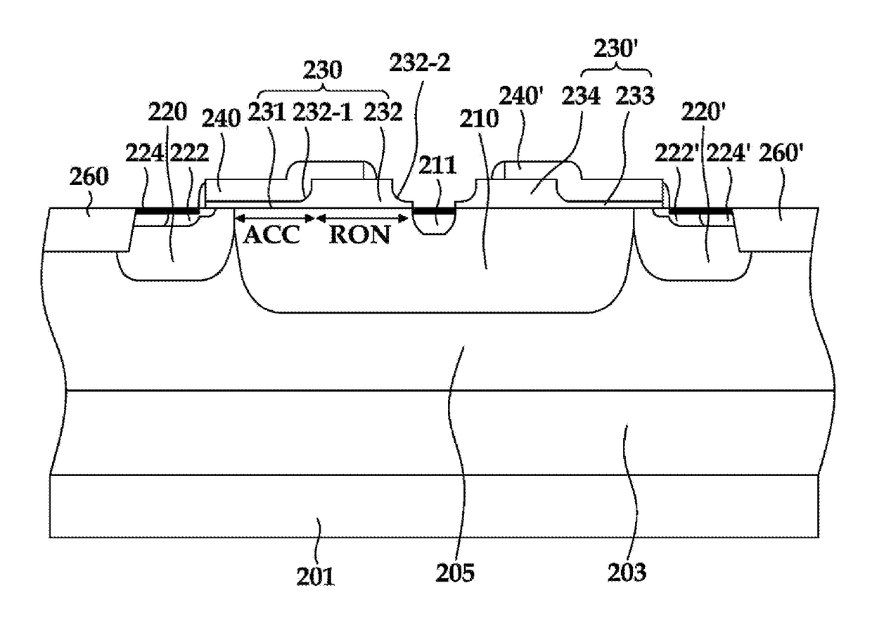
[0030]The present examples improve Rsp by minimizing the resistance of a drift region and increasing a breakdown voltage by changing a Laterally Diffused MOSFET (LDMOS) region into a stepped oxide layer form from a separated region STI made of a thin trench to form an n-type MOS or p-type MOS of Rsp with low resistance in a drift region.
[0031]In examples, the structure is changed from a separation region STI including a thin trench into a stepped oxide layer, and by making this change, an accumulation region length is reduced to a level of approximately 50% in comparison to a structure of a conventional STI region including thin trenches and thus, gate charge Qg is reduced to 60% in an otherwise identical device, providing advantages that are applicable to high frequency applications.

Problems solved by technology

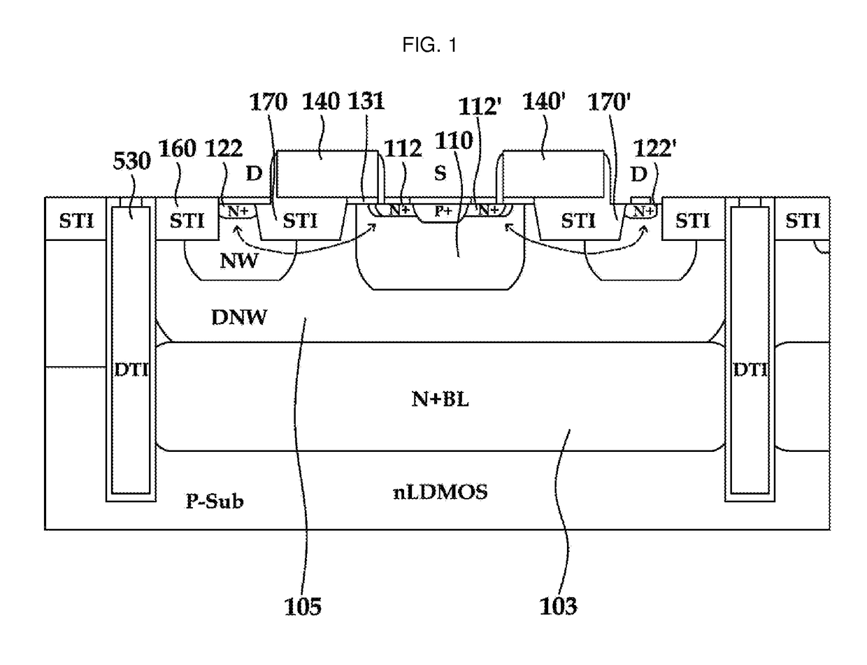
An accumulation region is formed on a drift region positioned below a gate insulator layer and there is a problem that arises when the length of the accumulation region extends a gate charge Qg value between regions of a gate and a drain or a gate and a source or a gate and a corresponding bulk increases.
As a result, then there is a problem that a Figure of Merit, hereinafter referred to as ‘FOM’, Ron×Qg, which is considered important in characterizing the performance of a high voltage device or electric device greatly increases.

Method used


Image

  • Semiconductor device
  • Semiconductor device
  • Semiconductor device

Examples


Embodiment Construction

[0043]The following detailed description is provided to assist the reader in gaining a comprehensive understanding of the methods, apparatuses, and / or systems described herein. However, various changes, modifications, and equivalents of the methods, apparatuses, and / or systems described herein will be apparent to one of ordinary skill in the art. The sequences of operations described herein are merely examples, and are not limited to those set forth herein, but may be changed as will be apparent to one of ordinary skill in the art, with the exception of operations necessarily occurring in a certain order. Also, descriptions of functions and constructions that are well known to one of ordinary skill in the art may be omitted for increased clarity and conciseness.

[0044]The features described herein may be embodied in different forms, and are not to be construed as being limited to the examples described herein. Rather, the examples described herein have been provided so that this disc...


PUM


Abstract

The present examples relate to a semiconductor device used in an electric device or high voltage device. The present examples improve Rsp by minimizing drift region resistance by satisfying breakdown voltage by improving the structure of a drift region through which current flows in a semiconductor device to provide optimal results. Moreover, a high frequency application achieves useful results by reducing a gate charge Qg for an identical device pitch to that of an alternative technology.

Description

CROSS-REFERENCE TO RELATED APPLICATION(S)[0001]This application claims the benefit under 35 USC 119(a) of Korean Patent Application No. 10-2014-0187468 filed on Dec. 23, 2014 in the Korean Intellectual Property Office, the entire disclosure of which is incorporated herein by reference for all purposes.BACKGROUND[0002]1. Field[0003]The following description relates to a semiconductor device. The following description also a semiconductor device used in an electric device or a high voltage device.[0004]2. Description of Related Art[0005]In understanding the functionality of an electric device or a high voltage device, there are two important features, which are a breakdown voltage blocking current flow in an off state and resistance that pertains when current flows at a switched-on state. These two features show appropriate trends because of use in a relevant silicon material. In other words, when breakdown voltage is high in a high voltage electric device, a drift region is low doped...

Claims


Application Information

Patent Timeline
Patent Type & Authority Patents(United States)
IPC IPC(8): H01L29/78H01L29/423H01L27/092H01L29/66H01L29/06H01L21/8238H01L29/10
CPCH01L29/7816H01L27/092H01L29/42368H01L29/7835H01L21/823878H01L21/823892H01L29/0653H01L29/1083H01L29/665H01L29/7809H01L29/7812H01L29/0886
Inventor RYU, YU SHINLEE, TAE HOONOH, BO SEOK
Owner KEY FOUNDRY CO LTD
Why Eureka
Try Eureka