Methods of repairing matrix cracks in melt infiltrated ceramic matrix composites

a technology of ceramic matrix and composites, which is applied in the direction of mechanical equipment, machines/engines, transportation and packaging, etc., can solve the problems of matrix cracks that are often subjected to loads above the matrix cracking stress, found their way into high temperature structural applications, and relatively expensive problems

Active Publication Date: 2017-07-11
GENERAL ELECTRIC CO
View PDF21 Cites 5 Cited by
  • Summary
  • Abstract
  • Description
  • Claims
  • Application Information

AI Technical Summary

Problems solved by technology

Monolithic ceramics, such as SiC ceramics, were developed many years ago but never found their way into high temperature structural applications because they lack damage tolerance and they fail catastrophically.
One current disadvantage of MI-CMCs is that they are relatively expensive, and therefore MI-CMC components need to be in working condition for extended periods of time to be economically viable.
Unfortunately during use in typical high temperature structural applications (e.g., gas turbine applications) MI-CMC components are often subjected to loads above the matrix cracking stress of the components.
The resulting cracks in the matrix portion of the components from such stresses act to decrease the stiffness and oxidation resistance of the MI-CMC composite, and can lead to premature failure of the MI-CMC component.
Further, temporary overstress conditions, such as from dropped parts or tools, can occur during MI-CMC component fabrication, transportation and / or installation and also can result in matrix cracks.

Method used


Image

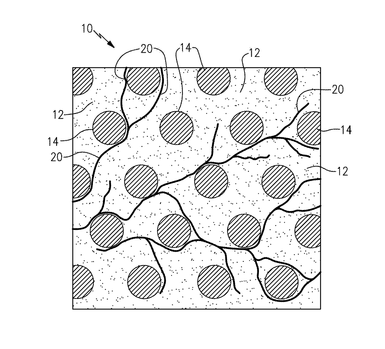
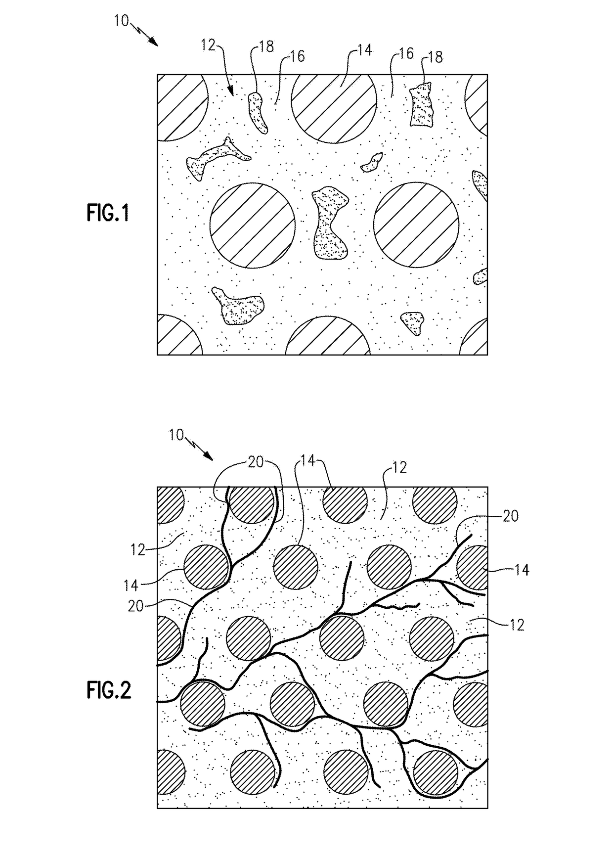
  • Methods of repairing matrix cracks in melt infiltrated ceramic matrix composites
  • Methods of repairing matrix cracks in melt infiltrated ceramic matrix composites
  • Methods of repairing matrix cracks in melt infiltrated ceramic matrix composites

Examples


example 1

[0026]Two panels of pre-impregnated MI-CMC, measuring about 6 in by 6 in by 0.08 in, were tested. The material of the panels is available under the trade name of HiPerComp™. The panels were cut into about 6 in long by 0.5 in wide MI-CMC bars. As-fabricated HiPerComp™ CMC is known to include residual stress in the matrix portion thereof that affects the measurement of the proportional limit stress of the material. To relieve such residual stress, six of the bars were annealed by either (a) heating them in air at about 2400° F. (about 1315° C.) for about 100 hours, (b) by reheating them for about 20 minutes above the melting point of silicon therein under a vacuum, or by using both treatments (a) and (b). The heat treated MI-CMC bars were then tested to failure at room temperature via a tensile test (using procedures as outlined in ASTM C1275) and the PL, E and ultimate strength of each heat treated MI-CMC bar were determined. The PL was determined using the 0.005% strain offset metho...

example 2

[0030]A panel of pre-impregnated MI-CMC material reinforced with coated Hi-Nicalon fiber was manufactured according to the procedures described in U.S. Patent Application No. 2007 / 0099527 and U.S. Pat. No. 6,024,898. Test MI-CMC bars were cut from this panel and subjected to the same testing procedures as described above with respect to EXAMPLE 1. Three MI-CMC bars were tensile strength tested in the annealed condition, one MI-CMC bar was tensile strength tested in the cracked condition, and two MI-CMC bars were tensile strength tested in the repaired condition as described above with respect to EXAMPLE 1. The results of the tensile strength testing of the annealed, cracked and repaired MI-CMC bars are listed in Table 2 below.

[0031]

TABLE 2Tensile Strength Test Results fromthe Test MI-CMC Bars from EXAMPLE 2Condition ofAverage ProportionalAverage InitialAverage UltimateSampleLimit Stress (ksi)Modulus (Msi)Strength (ksi)Annealed21.140.030.5Cracked12.529.931.8Repaired19.940.633.3

[0032]...


PUM

PropertyMeasurementUnit
temperatureaaaaaaaaaa
widthaaaaaaaaaa
temperatureaaaaaaaaaa

Abstract

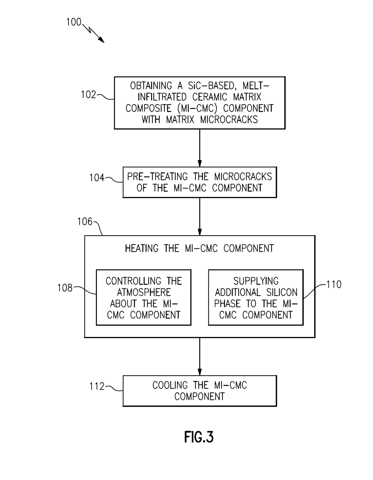
A method of repairing matrix microcracks in MI-CMC components includes heating “free” silicon phase present within the cracked matrix portion of the component to a temperature above the melting point of the silicon phase. During heating of the component an additional source of silicon phase is supplied to the component. The atmosphere about the component is controlled during the heating of the component. The MI-CMC component is cooled below the melting point of the silicon phase to cool and solidify the silicon phase that has migrated into the microcracks to thereby bond the crack faces together.

Description

BACKGROUND[0001]The present disclosure generally relates to methods and related configurations, components and assemblies of repairing cracks in ceramic matrix composites (CMCs), and in particular repairing matrix cracks in fiber-reinforced melt infiltrated ceramic matrix composites (MI-CMCs).[0002]Monolithic ceramics, such as SiC ceramics, were developed many years ago but never found their way into high temperature structural applications because they lack damage tolerance and they fail catastrophically. Ceramic matrix composites (CMCs), particularly those reinforced with fibers, were developed to alleviate the damage tolerance issues of monolithic ceramics and thereby have become attractive for high temperature structural applications, such as in gas turbine engines. One type of fiber-reinforced CMCs that is particularly attractive for high temperature structural applications is reactive melt infiltrated fiber-reinforced CMCs (hereinafter ‘MI-CMCs”).[0003]In MI-CMCs, a preform of...

Claims


Application Information

Patent Timeline
Patent Type & Authority Patents(United States)
IPC IPC(8): C03B29/00C04B37/00B29C73/00B29C65/00B32B37/00B65C9/25B29C73/16B23P6/04B29C73/02F01D5/00C04B41/85C04B41/00C04B41/50B23P6/00
CPCB29C73/00B23P6/045B29C73/02B29C73/16C04B41/009C04B41/5096C04B41/85F01D5/005C04B35/565C04B35/806C04B41/4515C04B41/4523C04B41/5094B23P6/002B23P6/04
Inventor CORMAN, GREGORY SCOT
Owner GENERAL ELECTRIC CO
Why Eureka
Try Eureka