
Energy-filtered cold electron devices and methods

a technology of energy filtering and cold electrons, applied in the field of electromechanical devices and methods for ultralow power dissipation electronics, can solve the problems of excessive power dissipation, significant degrade the performance of more mainstream electronic devices, etc., and achieve the effects of effective suppression, reducing electron temperature, and reducing power dissipation

Active Publication Date: 2017-07-11
BOARD OF RGT THE UNIV OF TEXAS SYST
View PDF7 Cites 1 Cited by
  • Summary
  • Abstract
  • Description
  • Claims
  • Application Information

AI Technical Summary

Benefits of technology

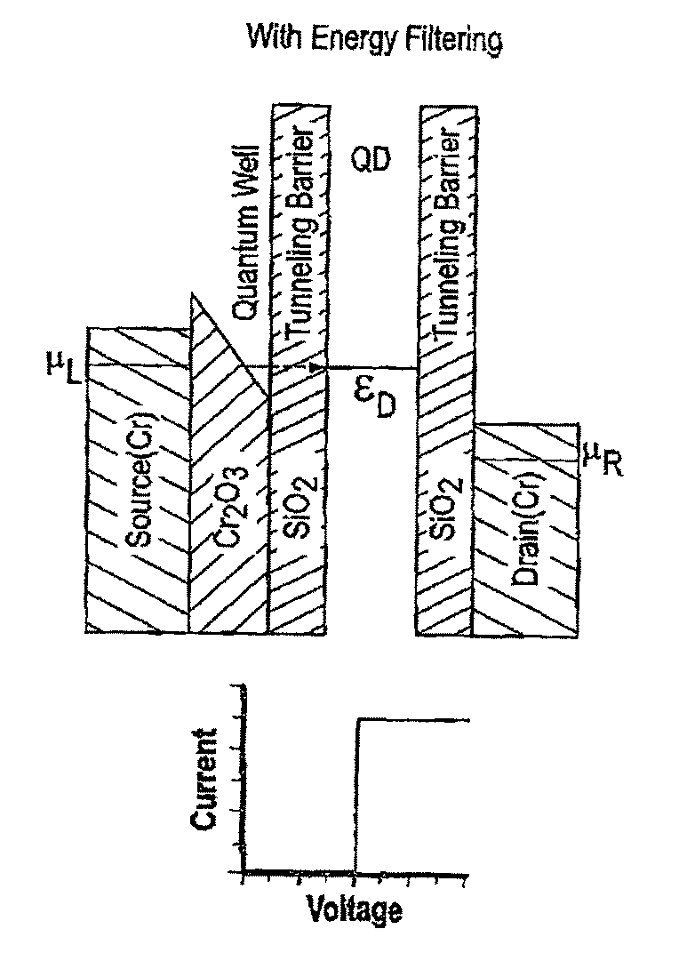
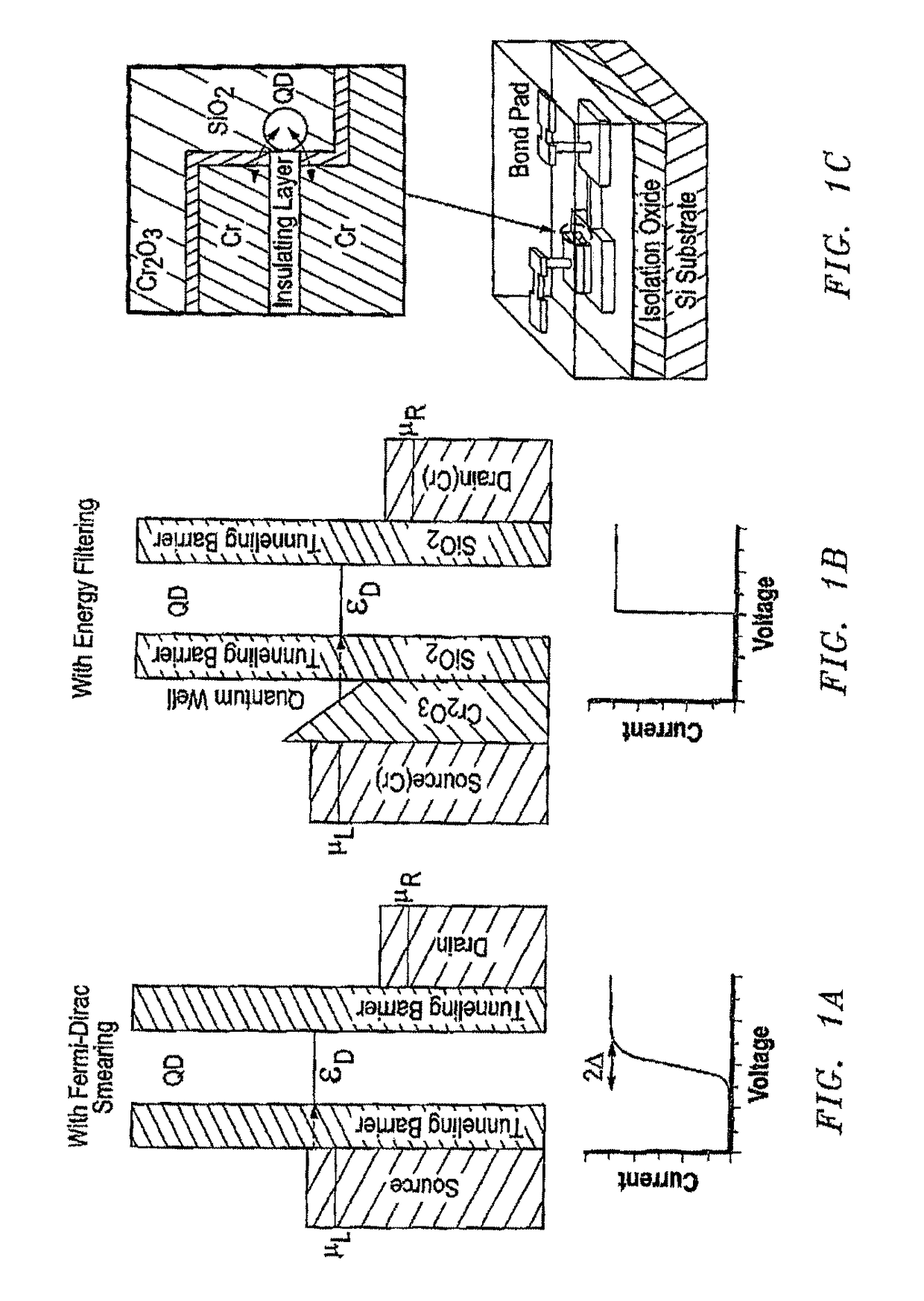
[0005]This present invention provides new electronic devices, hereinafter referred to as energy-filtered cold electron devices, which can effectively suppress the Fermi-Dirac electron thermal excitation, lower electron temperature, decrease power dissipation by achieving an extremely small subthreshold swing of less than 10 mV / decade at room temperature which in turn reduces the supply voltage to less than 0.1V. A discrete energy state obtained in the quantum well serves as an energy filter which can suppress the Fermi-Dirac smearing of electrons and hence effectively lower the electron temperature, leading to an extremely small subthreshold swing at room temperature. The present invention is primarily targeted at solving the problem of high power dissipation and power consumption in electronic devices, which can effectively increase the battery life of laptops, smart phones and other electronic gadgets. For military purposes, it is targeted at effectively reducing the weight of equipment carried by a soldier. This could mean a 90% reduction in total weight of equipment that requires battery power.
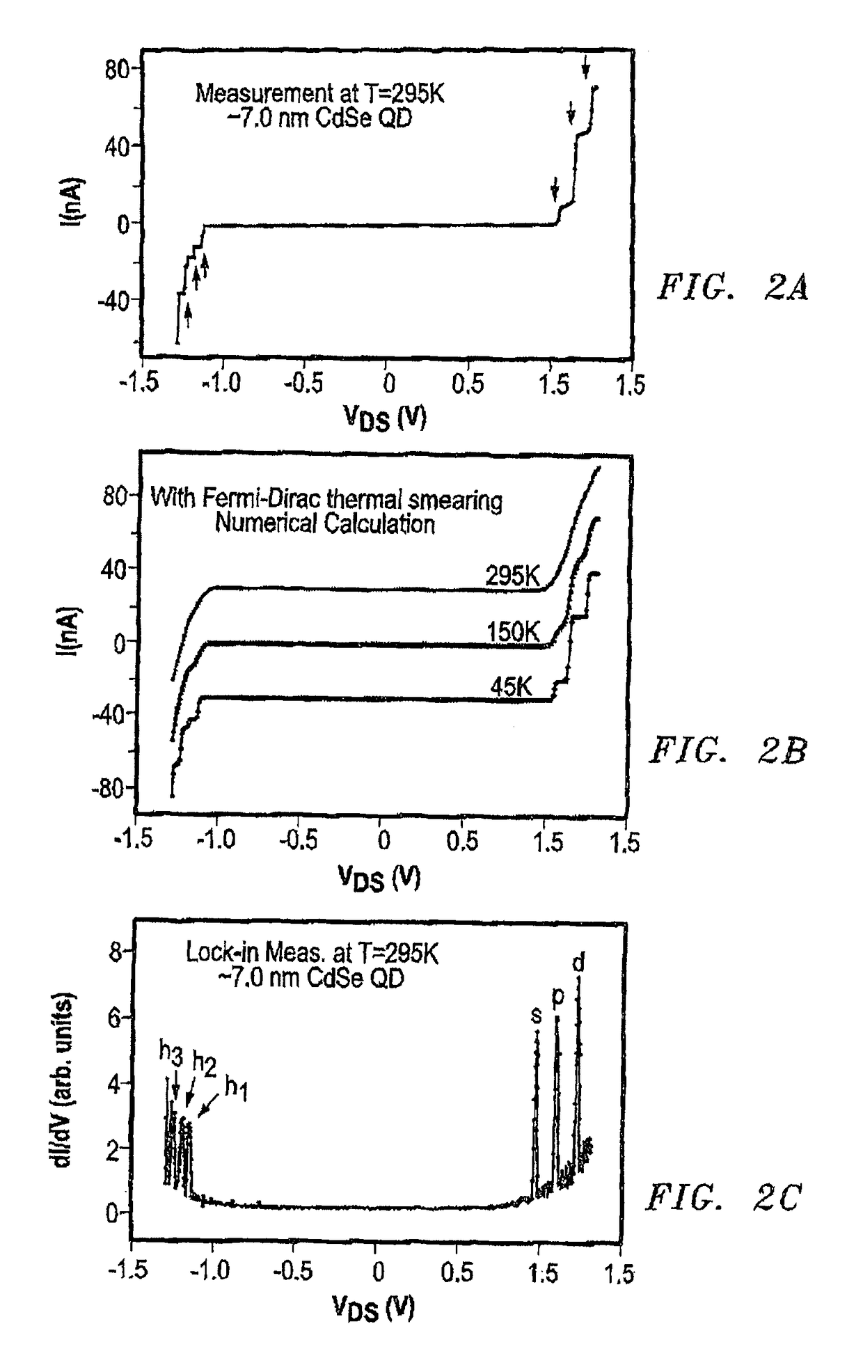
[0006]The present invention demonstrates that cold electrons whose effective temperature is as low as ˜45 K can be created and transported at room temperature without any physical cooling using a structure having a sequential arrangement of a source electrode, a quantum well (QW), a quantum dot (QD) and a drain electrode, in which a discrete state of the QW serves as an energy filter as electrons are transported from the source to the drain. The key aspect of this approach is that once electrons are filtered by the QW state, they cannot gain energy because no path exists for electron excitation (except for the phonon absorption), and therefore, the electrons remain cold until transported to the drain. This method holds promise for being used as a general strategy to raise the low-temperature operation regimes of various electron systems to room temperature or greatly enhance the performance of electron systems at room temperature. This is demonstrated with two examples. First, cold electrons are used in single-electron transistors, in which energy-filtered cold electrons eliminate the need of the cooling liquid and produce Coulomb staircase and Coulomb oscillations at room temperature. Second, the cold electrons enable an extremely steep current turn-on / off capability of ˜10 mV / decade at room temperature, a critical advancement that would pave routes to the realization of ultralow-power-dissipation electronics.

Problems solved by technology

Electron thermal excitation can also significantly degrade the performance of more mainstream electronic devices.
For example, it is the root cause of excessive power dissipation in metal-oxide-semiconductor field-effect transistors (MOSFET); the electron thermal excitation prevents a steep turning-on / off of electric current, limiting the subthreshold swing to ˜60 mV / decade at room temperature, causing ex cessive power dissipation [5-7].
Until now, studies have been focused on obtaining ultralow sub-Kelvin electrons and investigating their novel phenomena, while the entire system is cooled to cryogenic temperatures, typically less than 1 K [8-15], regimes not suitable for practical applications.

Method used


Image

  • Energy-filtered cold electron devices and methods
  • Energy-filtered cold electron devices and methods
  • Energy-filtered cold electron devices and methods

Examples


Embodiment Construction

[0052]While the making and using of various embodiments of the present invention are discussed in detail below, it should be appreciated that the present invention provides many applicable inventive concepts that can be embodied in a wide variety of specific contexts. The specific embodiments discussed herein are merely illustrative of specific ways to make and use the invention and do not delimit the scope of the invention.

[0053]Transistors that can operate with extremely low energy consumption would generate a lot of applications for military, commercial, and space use. For example, if the power consumption of battery-powered electronic devices can be reduced by ˜100 times, without sacrificing the performance, the battery weight of an instrument would be able to be reduced by ˜100 times. This would tremendously increase the capability of numerous military equipment, examples including unmanned aerial vehicles (UAVs), remote communication devices, remote sensing devices, missiles, ...


PUM


Abstract

Energy-filtered cold electron devices use electron energy filtering through discrete energy levels of quantum wells or quantum dots that are formed through band bending of tunneling barrier conduction band. These devices can obtain low effective electron temperatures of less than or equal to 45K at room temperature, steep electrical current turn-on / turn-off capabilities with a steepness of less than or equal to 10 mV / decade at room temperature, subthreshold swings of less than or equal to 10 mV / decade at room temperature, and / or supply voltages of less than or equal to 0.1 V.

Description

CROSS-REFERENCE TO RELATED APPLICATIONS[0001]This application is a U.S. national stage application under 35 U.S.C. §371 of International Application No. PCT / US2015 / 014258, filed Feb. 3, 2015, which claims priority pursuant to 35 U.S.C. §119 to U. S. Provisional Patent Application Ser. No. 61 / 935,493, filed Feb. 4, 2014, and U. S. Provisional Patent Application Ser. No. 62 / 032,554, filed Aug. 2, 2014, each of which is hereby incorporated by reference in its entirety.FIELD OF INVENTION[0002]The present invention relates generally to the field of electronics and, more particularly, to electronic devices and methods for ultralow-power-dissipation electronics.BACKGROUND ART[0003]At finite temperatures, electrons in solids are thermally excited in accordance with the Fermi-Dirac distribution. This electron thermal excitation obscures or nullifies many novel and technologically important phenomena in various electron systems. For example, it can wipe out the Coulomb blockade in single-elec...

Claims


Application Information

Patent Timeline
Patent Type & Authority Patents(United States)
IPC IPC(8): H01L29/66B82Y10/00H01L29/08H01L29/76B82Y40/00H01L29/41H01L29/24H01L29/06H01L29/12H01L29/88
CPCH01L29/66977B82Y10/00B82Y40/00H01L29/068H01L29/0673H01L29/0676H01L29/0895H01L29/122H01L29/127H01L29/24H01L29/413H01L29/66439H01L29/7613H01L29/882Y10S977/774Y10S977/937H01L29/66666H01L29/7827
Inventor KOH, SEONG JINBHADRACHALAM, PRADEEPMA, LIANG-CHIEH
Owner BOARD OF RGT THE UNIV OF TEXAS SYST
Learn More