Reticle shape regulation device and method, and exposure apparatus using same

a technology of reticle and shape regulation, which is applied in the field of photolithography, can solve the problems of complex and expensive solutions, serious deterioration of imaging performance, and irregular horizontal lines, and achieve the effect of satisfying flatness and easily creating vacuum

Active Publication Date: 2017-09-12
SHANGHAI MICRO ELECTRONICS EQUIP (GRP) CO LTD
View PDF6 Cites 0 Cited by
  • Summary
  • Abstract
  • Description
  • Claims
  • Application Information

AI Technical Summary

Benefits of technology

[0006]The present invention provides a device and a method for regulating a shape of a reticle and an exposure apparatus using the device and method, which can correct deformations of the reticle and enable satisfactory flatness thereof during the exposure process, thereby ensuring good performance of the process.
[0024]The present invention is advantageous over the prior art in that it can correct deformations of the reticle, thus enabling satisfactory flatness thereof during the exposure process, and can easily create vacuum and an air cushion between a deformed reticle and the adsorption device.

Problems solved by technology

However, such large reticles tend to experience deformations when they are lifted by suction, causing horizontal irregularities and deviations in the Z direction, some of which are up to 50 μm in some cases.
Serious deterioration in imaging performance will occur if such adverse impact is not properly controlled.
However, this solution is complex and costly and imposes high requirements on the projection objective.
However, this apparatus is associated with the problem that, as the sites are in fixed positional relationship with respect to the reticle, the negative pressures cannot be attained if the deformation is too large and forms a great gap between the reticle and attraction sites.

Method used


Image

  • Reticle shape regulation device and method, and exposure apparatus using same
  • Reticle shape regulation device and method, and exposure apparatus using same
  • Reticle shape regulation device and method, and exposure apparatus using same

Examples


Embodiment Construction

[0032]The above purposes, features and advantages of the present invention will become more apparent from the following description which is to be read in connection with the accompanying drawings. Note that the accompanying drawings are provided in a very simplified form not necessarily presented to scale, with the only purpose for convenience and clarity in explaining several specific embodiments of the invention.

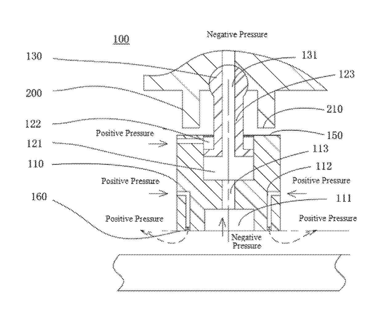
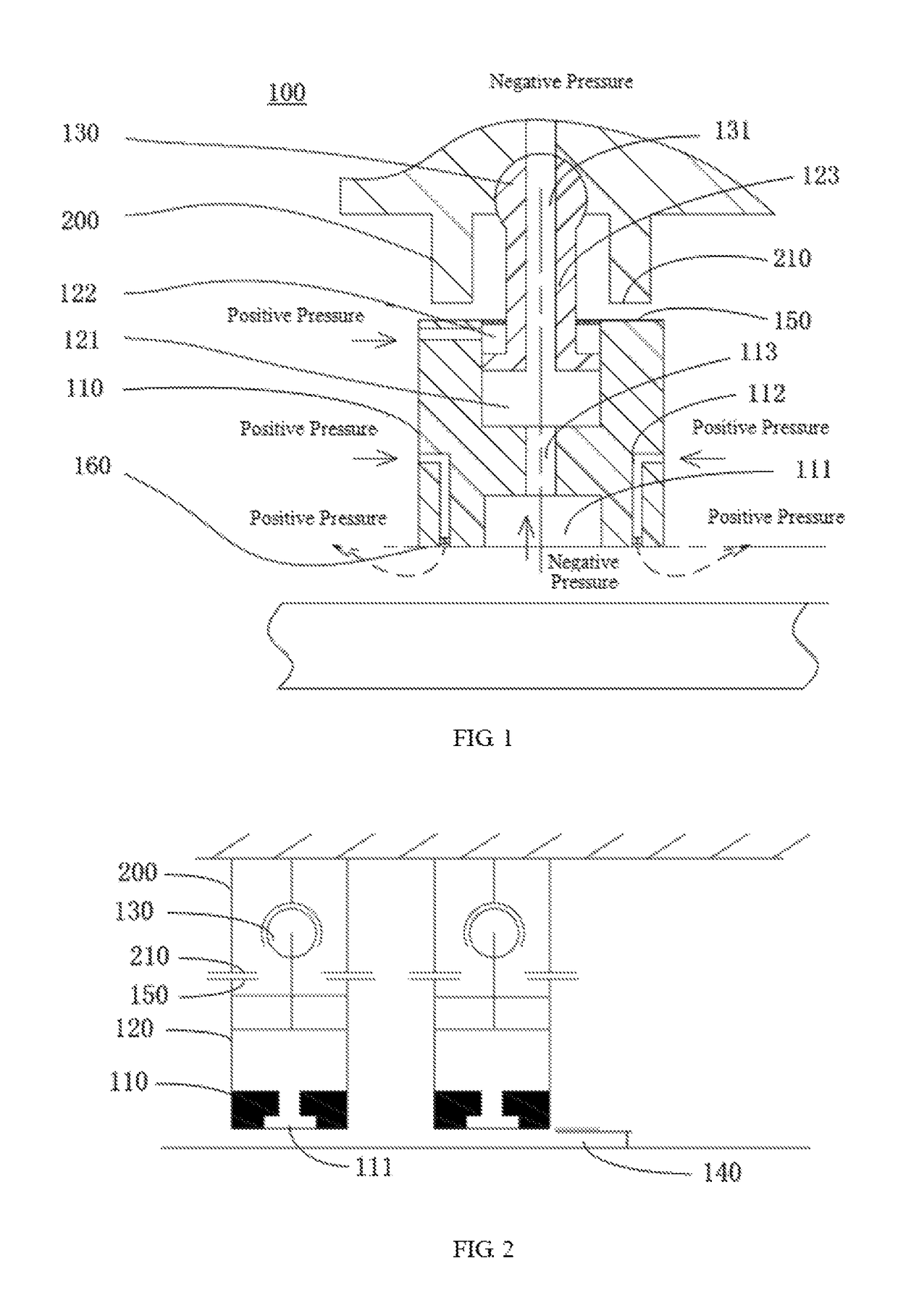
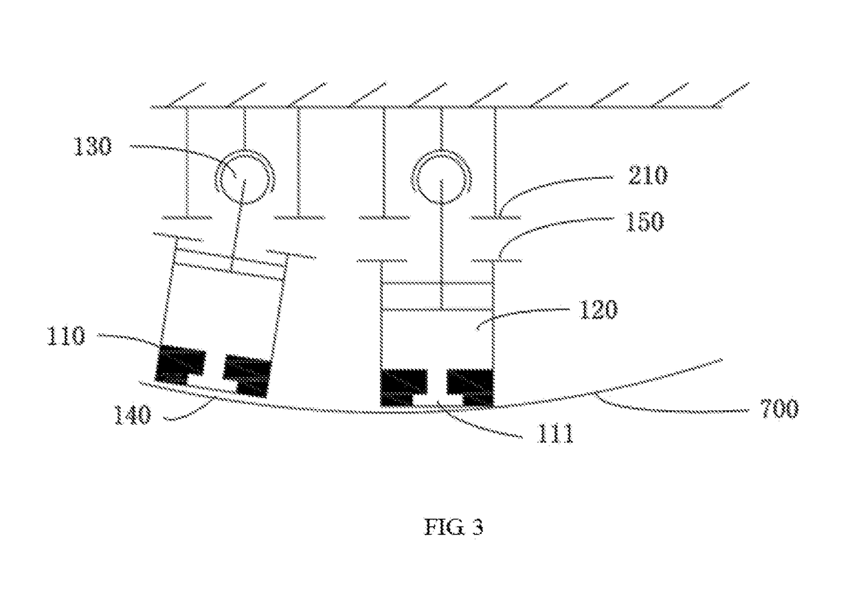
[0033]FIG. 1 shows a reticle shape regulation device 100 of the present invention. Referring to FIG. 1, in conjunction with FIGS. 2 to 3, the device includes an adsorption device 110 having an upper surface 150 and a lower surface 160. A pneumatic cylinder 120 is disposed within the adsorption device 110, and a piston 123 has one end located within the pneumatic cylinder 120 and the other end in movable connection with the limit mechanism 200 via a ball head link 130. The end of the piston 123 located in the pneumatic cylinder separates the pneumatic cylinder 120 into a p...


PUM

PropertyMeasurementUnit
sizeaaaaaaaaaa
reticle sizeaaaaaaaaaa

Abstract

A reticle shape regulation device includes: an adsorption device having an upper surface and a lower surface; and a limit mechanism having a limit surface. The adsorption device is movable relative to the limit mechanism at least in a vertical direction. The upper surface of the adsorption device faces toward and is engagable with the limit surface. The lower surface of the adsorption device defines a vacuum chamber that is configured for communication with a negative-pressure source so as to adsorb the reticle by a negative pressure. The lower surface of the adsorption device further defines at least one positive-pressure outlet that is in communication with a positive-pressure source and is configured to supply a continuous positive-pressure air flow between the lower surface of the adsorption device and the reticle during the adsorption of the reticle. The positive-pressure air flow is so controlled as to form an air cushion between the lower surface of the adsorption device and the reticle while allowing the adsorption of the reticle by the adsorption device. This can correct deformations of the reticle, thus enabling satisfactory flatness thereof during an exposure process, and can easily create vacuum and an air cushion between a deformed reticle and the adsorption device.

Description

TECHNICAL FIELD[0001]The present invention belongs to the field of photolithography and relates to a device and a method for regulating the shape of a reticle, in particular, a large reticle, and an exposure apparatus using the device and method.BACKGROUND[0002]Photolithography tools are mainly used in the manufacture of integrated circuits (ICs), flat panel displays and other micro devices. With a photolithography tool, distinct patterns formed in accurately-aligned respective reticles are successively transferred to a photoresist-coated wafer such as, for example, a semiconductor wafer or a wafer for forming a liquid crystal display (LCD). Photolithography tools are overall categorized into two types. A first type is called step-and-repeat systems (steppers), in which a reticle pattern is exposed onto an exposure area of a wafer in one shot, and the wafer is then moved relative to the reticle (or mask) to locate the next exposure area right under the reticle pattern interposed by ...

Claims


Application Information

Patent Timeline
Patent Type & Authority Patents(United States)
IPC IPC(8): G03F7/20
CPCG03F7/70783G03F7/707G03F7/708G03F7/70191G03F7/70691G03F7/70733G03F7/70791G03F7/70866
Inventor WANG, XINXINJIANG, XUCHUZHU, WENJINGWANG, XIAOGANG
Owner SHANGHAI MICRO ELECTRONICS EQUIP (GRP) CO LTD
Why Eureka
Try Eureka