Eureka AIR delivers breakthrough ideas for toughest innovation challenges, trusted by R&D personnel around the world.

Photovoltaic intensification system using solar tracking concentrators and heat exchangers

a technology of photovoltaic intensification and tracking concentrator, which is applied in the direction of pv power plants, electrochemical generators, light and heating equipment, etc., can solve the problems of poor skill development, low income security, poverty, etc., and achieve minimal financial investment, maximum solar energy accumulation, cost-effective

Active Publication Date: 2017-10-17
BEDELL ALFRED HYAMO
View PDF25 Cites 3 Cited by
  • Summary
  • Abstract
  • Description
  • Claims
  • Application Information

AI Technical Summary

Benefits of technology

[0013]Innovative technology in the photovoltaic intensification system removes these barriers by offering a pre-engineered solar system that significantly reduces the amount of solar cells needed, thereby lowering setup costs by more than 50%. Additionally, reflectors and solar cell cooling chambers are used to encapsulate added radiant energy. The photovoltaic intensification system is self-monitoring, and adjusts automatically using a microprocessor. In a prototype installation, the photovoltaic intensification system increased the solar energy measured (W / m2) and total solar energy collected (W / m2) by over 60% in a 12-hour charge period. The photovoltaic intensification system can be used in collaboration with drip irrigation, which is 95% more efficient than hand pumping. The photovoltaic intensification system provides farmers with cost-effective solar energy, and promotes a secure food network by increasing agricultural production using a renewable water supply. It will also reduce price shock due to food shortages.
[0026]In an aspect, the benefit of such technology as related to the current disclosed invention is the ability for developing countries, especially in the field of agriculture to have cost-effective solutions for energy demands. The intensified energies received from the current invention will allow small-scale farmers access to irrigation pumps, will provide an unlimited supply of free sustainable energy, and will create financial relief to the uncertain fluctuation of hydrocarbon fuels. Ultimately, this will assist in the reduction of carbon emissions and greenhouse gases.

Problems solved by technology

Poverty limits the development of food security for a number of reasons, including lack of market information, poor skill development, low security of income, inadequate credit for investment, a lack of electricity, and limited water supply.
On average, countries in Sub-Saharan Africa spend 5% of GDP, or $28.4 billion annually, on health spending and labor diversion due to poor sanitation and lack of clean water access.
Barriers to establishing a solar system and renewable water technology in developing countries include costly engineering assessments, high installation labor cost, the financial burden of buying equipment, lack of appropriate distribution channels, and insufficient business models.
This fact adds significant cost to the entire system.
This may present a barrier for implementation of technology in developing countries.

Method used


Image

  • Photovoltaic intensification system using solar tracking concentrators and heat exchangers
  • Photovoltaic intensification system using solar tracking concentrators and heat exchangers
  • Photovoltaic intensification system using solar tracking concentrators and heat exchangers

Examples


Embodiment Construction

[0047]Before describing the invention in detail, it should be observed that the present invention resides primarily in a novel and non-obvious combination of elements and process steps. So as not to obscure the disclosure with details that will readily be apparent to those skilled in the art, certain conventional elements and steps have been presented with lesser detail, while the drawings and specification describe in greater detail other elements and steps pertinent to understanding the invention.

[0048]The following embodiments are not intended to define limits as to the structure or method of the invention, but only to provide exemplary constructions. The embodiments are permissive rather than mandatory and illustrative rather than exhaustive.

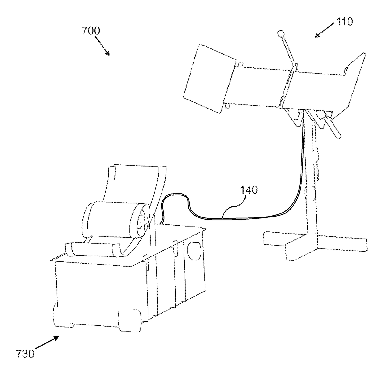
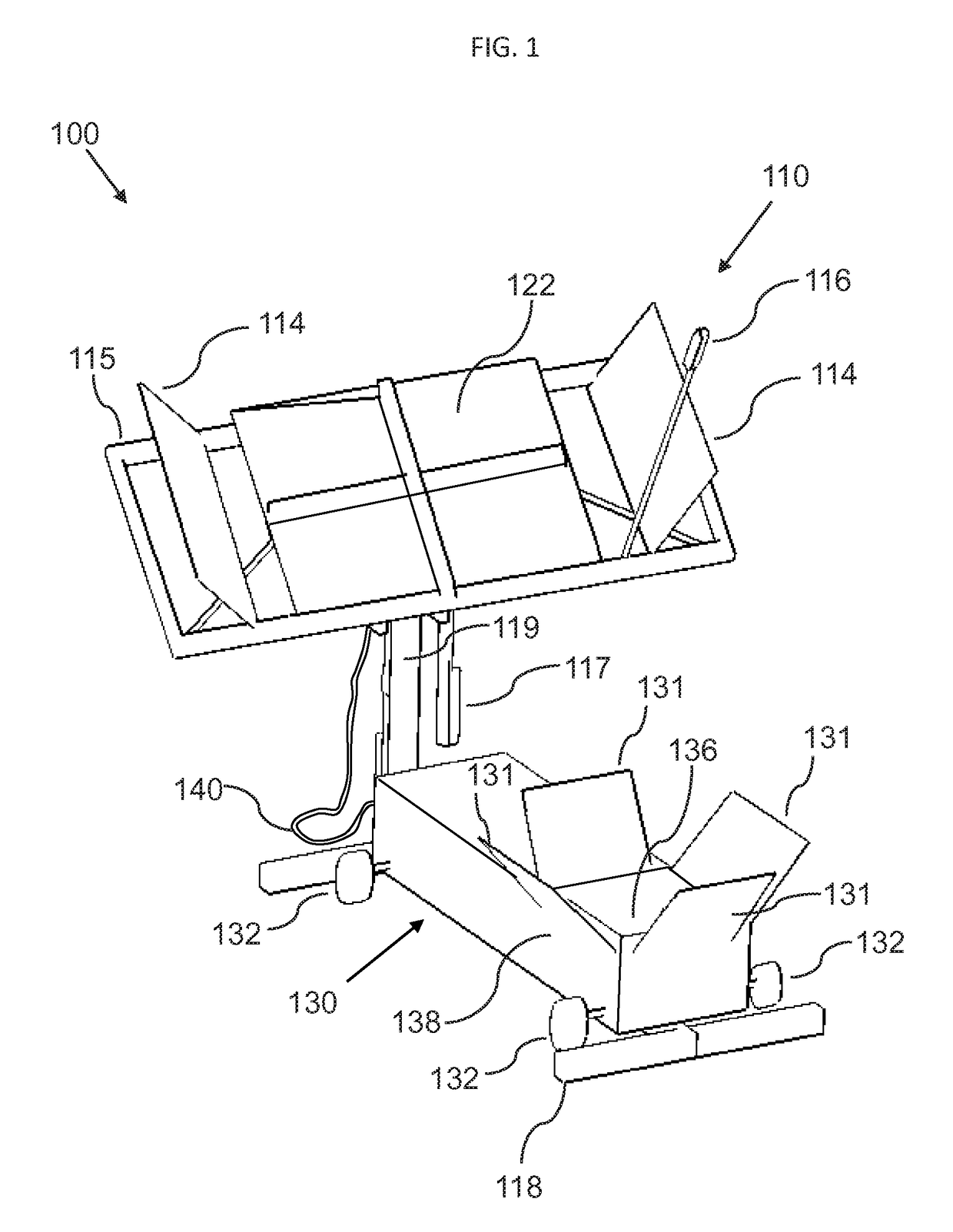
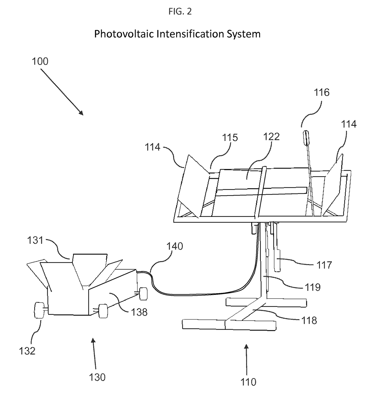
[0049]In the following, we describe the structure of an embodiment of a photovoltaic intensification system 100 with reference to FIG. 1, in such manner that like reference numerals refer to like components throughout; a convention that we s...


PUM

PropertyMeasurementUnit
angleaaaaaaaaaa
angleaaaaaaaaaa
heat resistantaaaaaaaaaa

Abstract

A photovoltaic intensification system includes a solar array stand, further including a mounting base; a mounting column; a solar array frame, a solar array, solar array lenses or reflectors, a light sensor, an elevation actuator, and a horizontal actuator; and a solar system cart, further including: a cart enclosure, a radiant solar cooker chamber, cart reflectors, and cart wheels. Further included are a vertical tilt ring, a strong-arm rod, a mass pivot rod, an elevation actuating ring, a horizontal tilt ring, and mounting brackets. A power and control system for photovoltaic intensification further includes a battery charger, a battery, an A / C inverter, a solar control unit, a remote control, a thermo electric freezer component, and a heat exchanger. A solar control unit includes a light sensor control circuit and a temperature control circuit, or a processor, a non-transitory memory, an input / output, an actuator controller, and a temperature controller.

Description

CROSS-REFERENCE TO RELATED APPLICATIONS[0001]This application claims the benefit of U.S. Provisional Application No. 61 / 910,408, filed Dec. 1, 2013, and U.S. Provisional Application No. 61 / 981,840, filed Apr. 20, 2014, both of which provisional applications are included herein by reference in their entirety.FIELD OF THE INVENTION[0002]The present invention relates generally to the technical field of energy production, and more particularly to the technical field of intensification of photovoltaic cells power generation by periodic alignment with radiant energy sources. The present invention also relates to solar tracking optimization systems for photovoltaic cells in a two axial movement system.BACKGROUND OF THE INVENTION[0003]It is projected that the world's population will increase by over two billion in the year 2050, with Sub-Saharan Africa having the highest population growth rate to over 2.4 billion in the next 40 years. In order to meet the need of a growing population, 60% m...

Claims


Application Information

Patent Timeline
Patent Type & Authority Patents(United States)
IPC IPC(8): H01L31/054F24J2/14F24J2/16F24J2/54F24J2/08H02J7/35F24J2/02H02S40/22H01M10/46H02S20/32F24J2/38F24S20/30F24S23/30F24S23/74F24S23/77F24S50/20
CPCH01L31/0543F24J2/02F24J2/08F24J2/14F24J2/16F24J2/541F24J2/542F24J2/5424H01M10/465H02J7/355H02S20/32H02S40/22F24J2/38Y02B40/18Y02E10/45Y02E10/47Y02E10/52H02S10/40F24S20/30F24S23/30F24S23/74F24S23/77F24S50/20F24S30/425F24S30/452F24S30/455H02J7/35Y02E10/56Y02E60/10Y02E10/40
Inventor BEDELL, ALFRED HYAMO
Owner BEDELL ALFRED HYAMO
Why Eureka
Eureka Blog
Learn More