Signal transmission device, receiving circuit, and electronic apparatus

a technology of signal transmission device and receiving circuit, which is applied in the direction of duplex signal operation, baseband system details, fixed station waveguide transmission system, etc., can solve the problems of increasing power consumption, increasing signal distortion effect, and increasing unnecessary radiation, so as to reduce interference problems

Inactive Publication Date: 2017-10-17
SONY CORP
View PDF38 Cites 8 Cited by
  • Summary
  • Abstract
  • Description
  • Claims
  • Application Information

AI Technical Summary

Benefits of technology

[0022]In the first and second signal transmission devices of the present disclosure, the receiving circuits according to the third and fourth aspects, and the electronic apparatuses according to the fifth and sixth aspects of the present disclosure, it is possible to reduce the interference problem with another channel without employing a method of increasing a frequency difference between channels in a simple configuration.

Problems solved by technology

However, due to recent new large amounts of transmission data at high speeds, problems such as an increase of power consumption, an increase of signal distortion effects due to reflection or the like, and an increase of unnecessary radiation occur.
For example, LVDS has reached a limitation when signals such as an image signal (including an imaging signal) or a computer image are transmitted in the apparatus at a high speed (in real time).
However, this method causes an increased number of input and output terminals.
As a result, for example, a complicated printed circuit board or cable wire or an increase of a semiconductor chip size is necessary.
In addition, an electromagnetic interference problem occurs due to transmission of large amounts of high speed data through the wire.
Problems in both of the LVDS and the method of increasing the number of wires occur due to signal transmission through the electric wire.

Method used


Image

  • Signal transmission device, receiving circuit, and electronic apparatus
  • Signal transmission device, receiving circuit, and electronic apparatus
  • Signal transmission device, receiving circuit, and electronic apparatus

Examples


embodiment 1

[Details of Millimeter-Wave Band Signal Transmission Function]

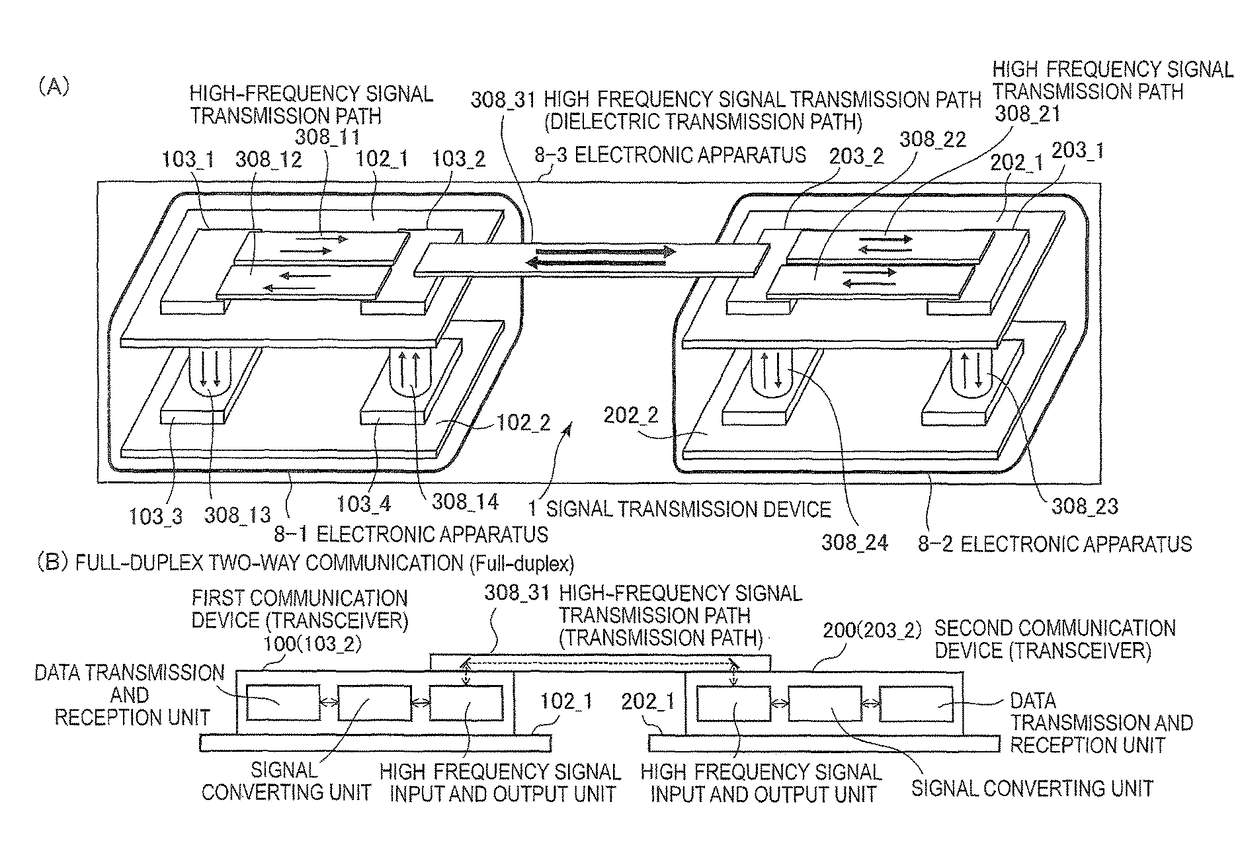
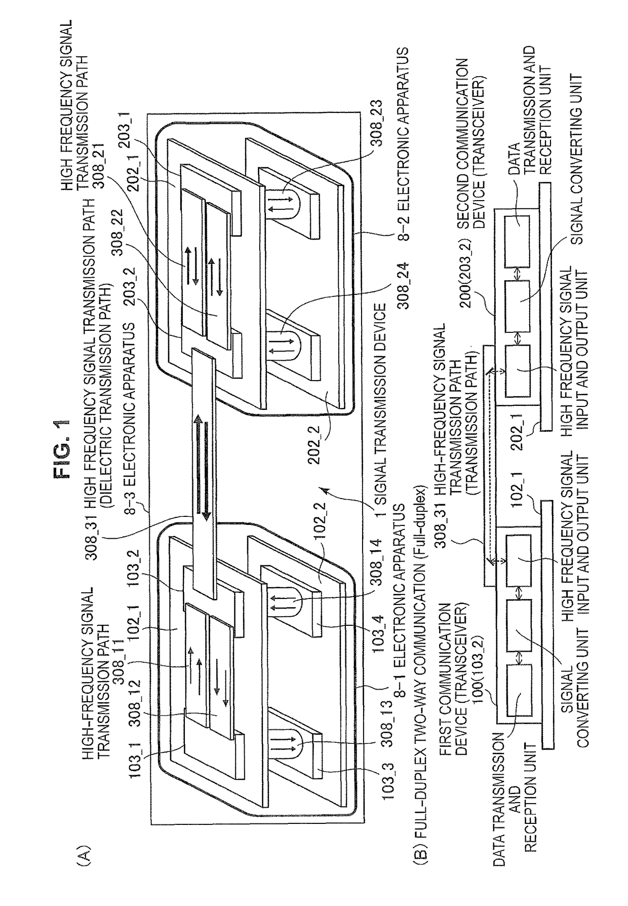
[0169]Embodiment 1 is an application example of a mutual interference countermeasure in a configuration corresponding to the full-duplex two-way communication. FIG. 11 is a diagram illustrating transmission and reception systems according to Embodiment 1, and is a functional block diagram of Embodiment 1, focusing on a signal transmission function from a modulation function unit to a demodulation function unit through the high frequency signal waveguide 308 (the signal transmission path 9). FIG. 11 illustrates a configuration corresponding to full-duplex two-way communication of a low frequency side (for example, a 57 GHz band and 12.5 gigabits per second (Gb / s)) and a high frequency side (for example, an 80 GHz band and 12.5 Gb / s).

[0170]In a signal transmission device 1(A) according to Embodiment 1, the first communication device 100 uses a carrier frequency of the high frequency side (80 GHz band) in a transmission proc...

embodiment 2

[Details of Millimeter-Wave Signal Transmission Function]

[0185]FIG. 13 is a diagram illustrating transmission and reception systems according to Embodiment 2 and is a functional block diagram according to Embodiment 2, focusing on a signal transmission function from a modulation function unit to a demodulation function unit through the high frequency signal waveguide 308 (the signal transmission path 9). FIG. 13 illustrates a configuration corresponding to the simplex two-way communication of a low frequency side (for example, a 57 GHz band and 12.5 Gb / s) and a high frequency side (for example, an 80 GHz band and 12.5 Gb / s). In addition, it is preferable to configure the transmission processing unit (a circuit composed of two amplifiers 4, and a peripheral circuit thereof) or the reception processing unit (a circuit composed of two low-noise amplifiers 400, and a peripheral circuit thereof) as a single chip.

[0186]Embodiment 2 is an application example of a mutual interference counte...

embodiment 3

[0195]Embodiment 3 is an application example of a mutual interference countermeasure in a configuration when the full-duplex two-way communication and the simplex two-way communication are combined. Here, the most fundamental example including three channels will be described. Unlike Embodiment 4 to be described below, in the simplex two-way communication, it is assumed that a mutual interference countermeasure (that is, the method according to Embodiment 2) is unnecessary between transmission-sides and between reception-sides. That is, Embodiment 1 is applied when the full-duplex two-way communication is applied in a combination of two channels which are adjacent to each other. A leakage path of a simplex two-way communication system is not considered.

[0196]Hereinafter, in a relation of three channels, “Low” indicates a low frequency channel (57 GHz band). “Mid” indicates a mid frequency channel (80 GHz band). “High” indicates a high frequency channel (103 GHz band). When a desired...


PUM


Abstract

There is provided a signal transmission device including reception processing units for respective channels, so as to enable multichannel transmission by dividing frequency bands. The total number of channels is equal to or greater than three. When full-duplex two-way communication is applied in any combination of two channels, one of reception processing unit include a signal suppressing unit configured to suppress a signal component of a channel other than a self channel.

Description

TECHNICAL FIELD[0001]The present invention relates to a signal transmission device, a receiving circuit, and an electronic apparatus, and more specifically, to technology for addressing mutual interference when multichannel transmission is performed.BACKGROUND ART[0002]Today, in signal transmission inside an electronic apparatus or between electronic apparatuses, technology capable of processing or transmitting a large amount of data at a high speed (for example, in real time) is necessary. In related art, signals have been typically transmitted through an electric wire. For example, low voltage differential signaling (LVDS) has been known as a method for implementing high speed signal transmission. However, due to recent new large amounts of transmission data at high speeds, problems such as an increase of power consumption, an increase of signal distortion effects due to reflection or the like, and an increase of unnecessary radiation occur. For example, LVDS has reached a limitat...

Claims


Application Information

Patent Timeline
Patent Type & Authority Patents(United States)
IPC IPC(8): H04Q11/02H04B1/10H04J1/12H04B10/25H04J1/02H04B3/52H04L5/16H04L5/14H04L25/03
CPCH04B10/2503H04B1/1036H04B3/52H04J1/02H04J1/12H04L5/14H04L5/16H04L2025/03426H04B10/2589
Inventor HINO, YASUFUMI
Owner SONY CORP
Why Eureka
Try Eureka