Temperable three layer antirefrlective coating, coated article including temperable three layer antirefrlective coating, and/or method of making the same

a three-layer antirefrlective coating and coating technology, applied in coatings, instruments, optics, etc., can solve the problems of creating additional problems, undesirable tempering coat methods, and difficult to so as to reduce the reflection of visible light and achieve optimal refraction index

Active Publication Date: 2017-10-24
GUARDIAN GLASS LLC
View PDF56 Cites 60 Cited by
  • Summary
  • Abstract
  • Description
  • Claims
  • Application Information

AI Technical Summary

Problems solved by technology

Achieving this optimal index of refraction is difficult however.
However, this “temper then coat” method may be undesirable in certain circumstances.
Further, a coat then temper technique may create additional problems.
When glass is coated and then tempered, the result of the tempering process may produce undesirable optical flaws in the overall glass product.
For example, the color shift, or ΔE, in the tempered, coated glass product may render the glass unusable.

Method used


Image

  • Temperable three layer antirefrlective coating, coated article including temperable three layer antirefrlective coating, and/or method of making the same
  • Temperable three layer antirefrlective coating, coated article including temperable three layer antirefrlective coating, and/or method of making the same
  • Temperable three layer antirefrlective coating, coated article including temperable three layer antirefrlective coating, and/or method of making the same

Examples


example 1

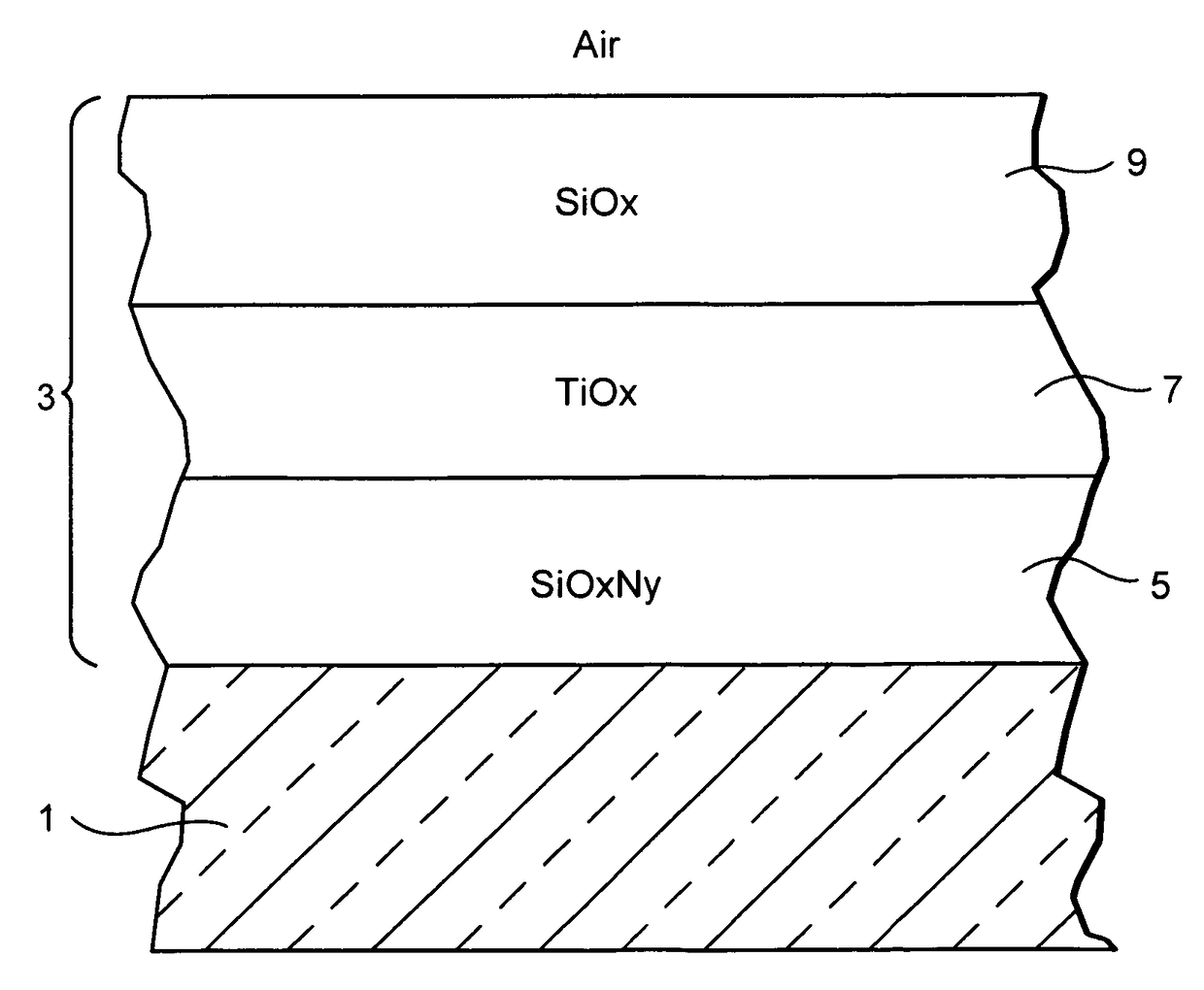
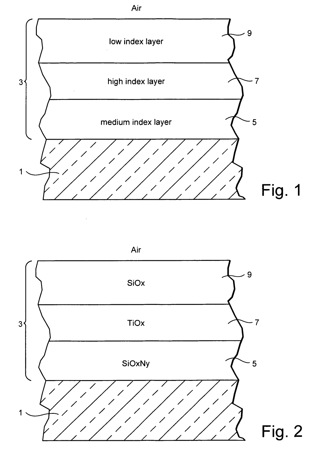
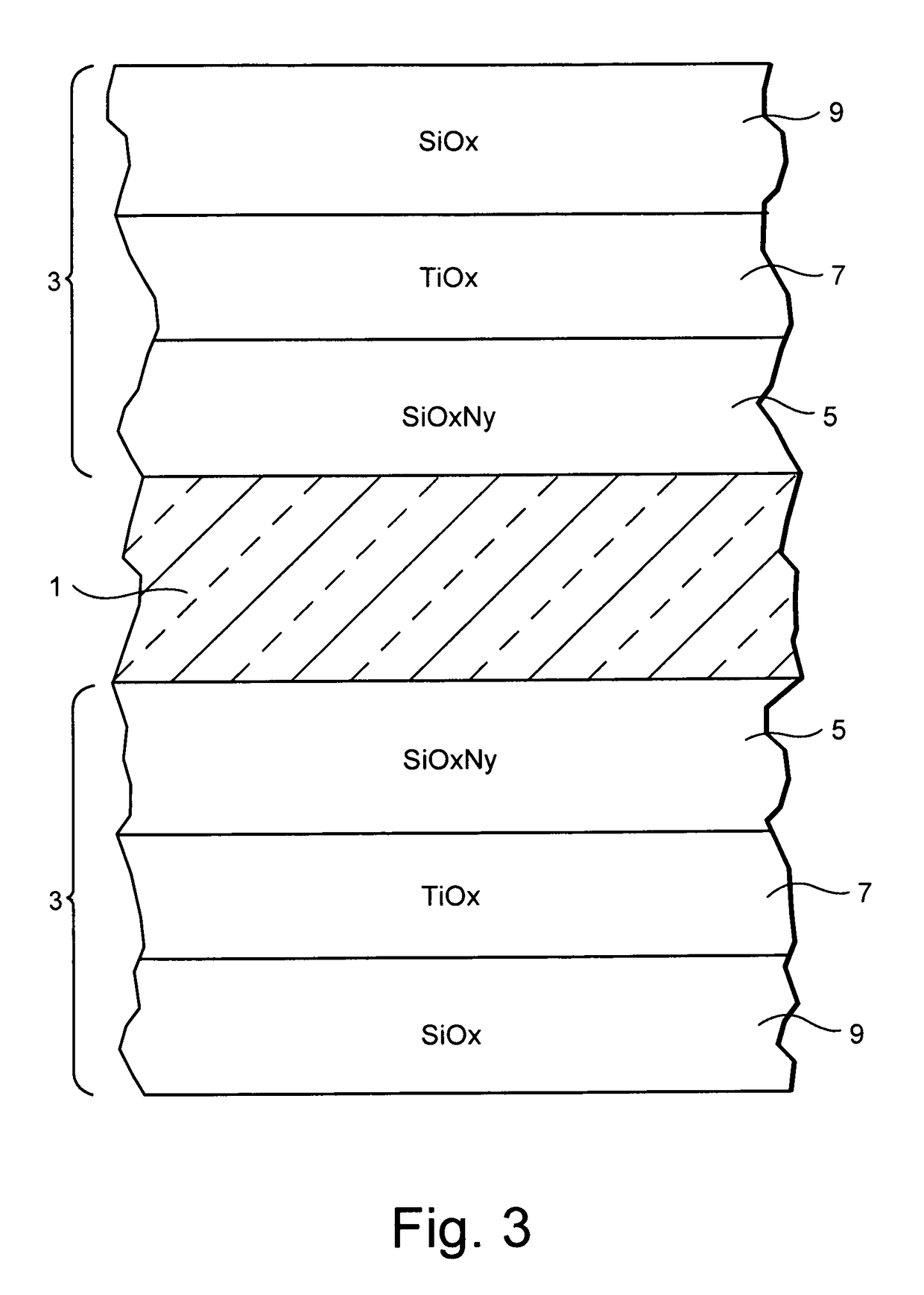
[0060]An Example AR coating 3 was made as follows: SiOxNy layer 5 (medium index layer) about 95 nm thick, TiO2 layer 7 (example high index layer) about 21 nm thick, and SiO2 layer 9 (example low index layer) about 105 nm thick. The clear glass substrate was about 5 mm thick, and was soda lime silica type glass. Each of layers 5, 7, and 9 was deposited on the glass substrate 1 by sputtering a target(s). The coating 3 was provided on only one major surface of the glass substrate in certain instances as shown in FIG. 1, but may be provided on both major surfaces of the glass substrate in other instances as shown in FIG. 3. The coating was tempered at 650 degrees C. for 10 minutes.

[0061]FIG. 4 is a graph showing a comparison of the first surface reflectivity of an as-coated and a tempered / heat-treated three layer visible AR coating at an 8 degree incident angle using White Light. FIG. 4 illustrates the reflection spectra of an example having SiOxNy adjusted to achieve a refractive index...

example 2

[0069]A temperable AR coating was applied to both surfaces of a glass substrate (e.g., a double sided coating was made).

[0070]The double-sided coating (as shown in FIG. 3) also maintains its optical and aesthetic qualities after tempering / heat-treatment processes, when coated on the Sn side of float glass, without the need for any additional surface preparation such as polishing. The coating design described in the preceding paragraphs with respect to Example 1 can be applied to the second surface (or Sn side) of the glass to reduce the overall reflection from both interferences.

[0071]FIG. 10 illustrates the light transmission achieved with the above-described design applied to both surfaces of low iron glass before and after tempering / heat-treating. The photopic light transmission increases after exposure to a tempering environment and exceeds 99% at normal incidence on 3.2 mm low iron glass.

[0072]FIG. 11 illustrates example ranges of physical thicknesses and refractive indices for...


PUM

PropertyMeasurementUnit
thicknessaaaaaaaaaa
thicknessaaaaaaaaaa
thicknessaaaaaaaaaa

Abstract

A coated article includes a temperable antireflection (AR) coating that utilizes medium and low index (index of refraction “n”) layers having compressive residual stress in the AR coating. In certain example embodiments, the coating may include the following layers from the glass substrate outwardly: silicon oxynitride (SiOxNy) medium index layer / high index layer / low index layer. In certain example embodiments, depending on the chemical and optical properties of the high index layer and the substrate, the medium and low index layers of the AR coating are selected to cause a net compressive residual stress.

Description

CROSS-REFERENCE TO RELATED APPLICATION[0001]This application is a continuation-in-part (CIP) of U.S. application Ser. No. 12 / 923,146 filed Sep. 3, 2010, the entire contents of which are hereby incorporated herein by reference.FIELD OF THE INVENTION[0002]Certain example embodiments of this invention relate to a coated article including a temperable antireflective coating, and / or a method of making the same. In certain example embodiments, a temperable antireflective (AR) coating utilizes SiOxNy as the medium index layer of the coating. In certain example embodiments, the coating may include the following layers from the glass substrate outwardly: silicon oxynitride (e.g., SiOxNy) as the medium index layer / titanium oxide (e.g., TiOx) as the high index layer / silicon oxide (e.g., SiOx) as the low index layer. In certain example embodiments, the thicknesses and / or types of stress in each layer may be optimized in order to produce a temperable, three layer antireflective coating.BACKGROUN...

Claims


Application Information

Patent Timeline
Patent Type & Authority Patents(United States)
IPC IPC(8): G02B1/11C03C17/34G02B1/115
CPCC03C17/3435G02B1/115C03C2218/365C03C2217/73
Inventor BROADWAY, DAVID M.LU, YIWEI
Owner GUARDIAN GLASS LLC
Why Eureka
Try Eureka