Low-power method and device for cooling prosthetic limb socket based on phase change

a prosthetic limb and phase change technology, applied in the field of low-power method and device for cooling prosthetic limb sockets based on phase change, can solve the problems of increasing skin temperature, poor thermal conductivity, and limited heat transfer from residual limbs through prosthetic devices to the exterior environment, and achieves short settle time, efficient and portable

Active Publication Date: 2017-11-14
THE UNIVERSITY OF AKRON
View PDF12 Cites 6 Cited by
  • Summary
  • Abstract
  • Description
  • Claims
  • Application Information

AI Technical Summary

Benefits of technology

[0006]The present invention provides a residual limb-prosthesis to regulate temperature on the inner surface of a prosthetic socket. The cooling device uses an adjustable thermal resistance to adapt to various activity patterns and environments in a short settling time. To make the device efficient and portable, heat pipes are used to concentrate heat flux from the residual limb into a compact heat sink, where heat is removed by a compact fan / air duct.
[0009]In a third embodiment, the present invention provides a residual limb-prosthesis as in the first or second embodiments, wherein the control system includes a heat sensor for monitoring temperature at an interface between a residual limb and the socket, further communicating with a regulator which regulates the effectiveness of the heat sink.

Problems solved by technology

Heat transfer from a residual limb through a prosthetic device and to the exterior environment is currently limited by poor thermal conductivity of the prosthesis's liner and socket material.
The closed environment of the socket of a prosthesis also prevents heat transfer through evaporation (sweating), thereby increasing skin temperature that may cause skin blisters and irritation.
Many amputees report that heat and perspiration within a prosthetic socket provide significant discomfort, and the art has moved to provide certain prosthesis cooling systems.
Hence it remains a challenge to maintain a comfortable socket temperature in various environments while performing different activities.
Due to limited contact area and low heat capacity of air, heat transfer is ineffective and therefore the cooling capacity is insufficient to remove additional heat.
This type of cooling system has a high coefficient of convective heat transfer which reduces the thermal resistance between a liner and the environment.
However, comfortably using a liquid cooling system requires small diameter tubing, which translates to high power consumption for liquid circulation.
Due to the relatively bulky and power intensive equipment needed for this type of liquid cooling system, a tradeoff has to be made between functionality and comfortableness.
However, controlling the cooling rate over various thermal loads remains a difficulty for PCM systems.

Method used


Image

  • Low-power method and device for cooling prosthetic limb socket based on phase change
  • Low-power method and device for cooling prosthetic limb socket based on phase change
  • Low-power method and device for cooling prosthetic limb socket based on phase change

Examples


Embodiment Construction

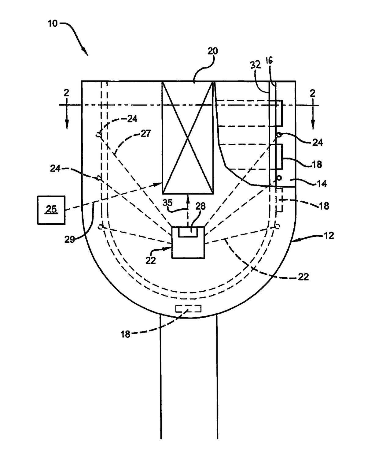
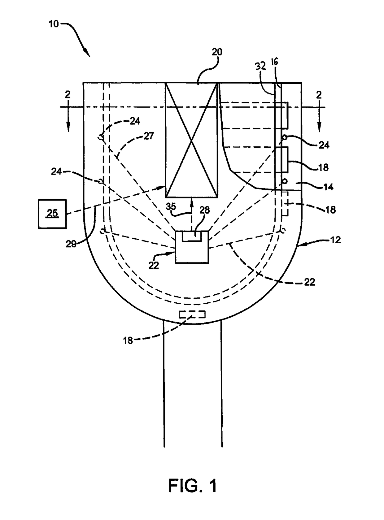
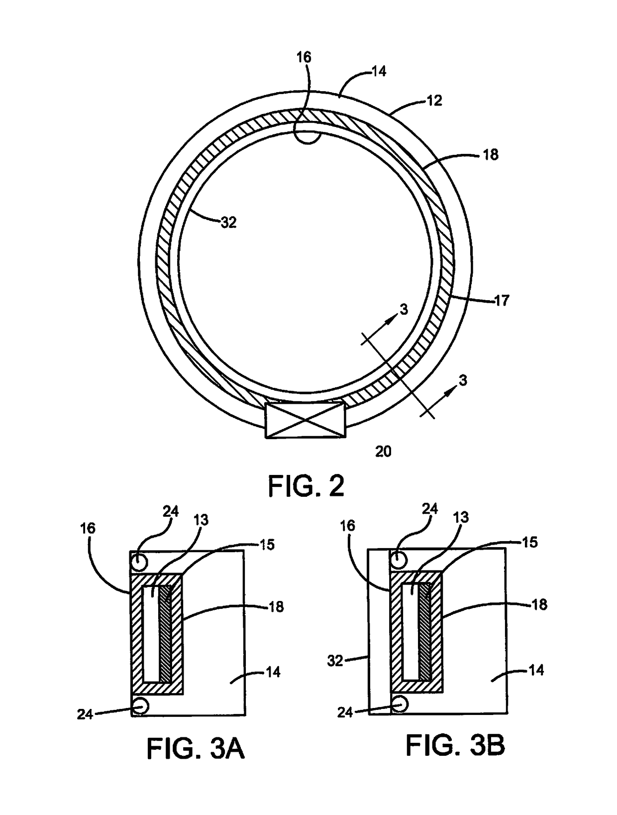
[0044]With reference to FIGS. 1-3, a generic embodiment of a residual limb-prosthesis is shown and designated by the numeral 10. The residual limb-prosthesis 10 includes a socket 12 for receiving a residual limb, wherein the socket 12 includes a socket wall 14 defining a limb-receiving surface 16. The socket 12 can be manufactured from any of the common materials employed for prosthesis sockets in the prior art or hereinafter developed.

[0045]At least one heat pipe 18 extends through at least a portion of the socket 12 and includes a working fluid 13 (FIG. 3) and a wicking structure 15. The heat pipe 18 includes a socket section 17 (FIG. 1) and a heat sink section 19, wherein the heat pipe 18 extends along its length through said socket wall 14 proximate to or exposed at the limb-receiving surface 16. In some embodiments, multiple heat pipes may be employed. The heat pipes can extend in the same or different directions and can be placed at various locations, whether horizontally or v...


PUM


Abstract

A prosthesis includes a socket for receiving a residual limb, the socket having a socket wall defining a limb-receiving surface; a heat pipe including a working fluid and a wicking structure, the heat pipe having a socket section and a heat sink section, the heat pipe extending along its length through the socket wall proximate to or exposed at the limb-receiving surface, wherein the working fluid has a boiling point of from about 0° C. to 90° C. such that the working fluid is adapted to evaporate to form vapor under the influence of the heat of a residual limb in the socket thus drawing heat from and cooling the residual limb. A heat sink section of the heat pipe passes through the heat sink, the heat sink reducing the temperature of the working fluid.

Description

CROSS-REFERENCE TO RELATED APPLICATIONS[0001]The present application claims priority to U.S. Provisional Patent Application Ser. No. 61 / 820,233, filed May 7, 2013, the entirety of which is incorporated herein by reference.BACKGROUND OF THE INVENTION[0002]Heat transfer from a residual limb through a prosthetic device and to the exterior environment is currently limited by poor thermal conductivity of the prosthesis's liner and socket material. The closed environment of the socket of a prosthesis also prevents heat transfer through evaporation (sweating), thereby increasing skin temperature that may cause skin blisters and irritation. Many amputees report that heat and perspiration within a prosthetic socket provide significant discomfort, and the art has moved to provide certain prosthesis cooling systems.[0003]Maintaining a normal temperature at the skin-prosthesis interface under various activities (thermal loads) is a fundamental design requirement for a prosthesis cooling system....

Claims


Application Information

Patent Timeline
Patent Type & Authority Patents(United States)
IPC IPC(8): A61F2/80A61F7/10A61F2/50A61F2/74A61F7/00A61F2/76
CPCA61F2/80A61F7/10A61F2002/501A61F2002/74A61F2007/108A61F2007/0051A61F2007/0058A61F2007/0086A61F2007/105A61F2002/7665A61F2/74
Inventor ZHE, JIANGHAN, YU
Owner THE UNIVERSITY OF AKRON
Why Eureka
Try Eureka