
Method for localised repair of a damaged thermal barrier

a thermal barrier and localization technology, applied in the direction of electrophoretic coatings, mechanical equipment, machines/engines, etc., can solve the problems of thermal barrier damage that may even need to be discarded, certain zones of the system may be damaged in high temperature service, and oxidation of the underlying part, so as to enhance the deposition of ceramic coatings and improve the electrically conductive nature of damaged zones.

Active Publication Date: 2017-12-12
SN DETUDE & DE CONSTR DE MOTEURS DAVIATION S N E C M A +3
View PDF5 Cites 1 Cited by
  • Summary
  • Abstract
  • Description
  • Claims
  • Application Information

AI Technical Summary

Benefits of technology

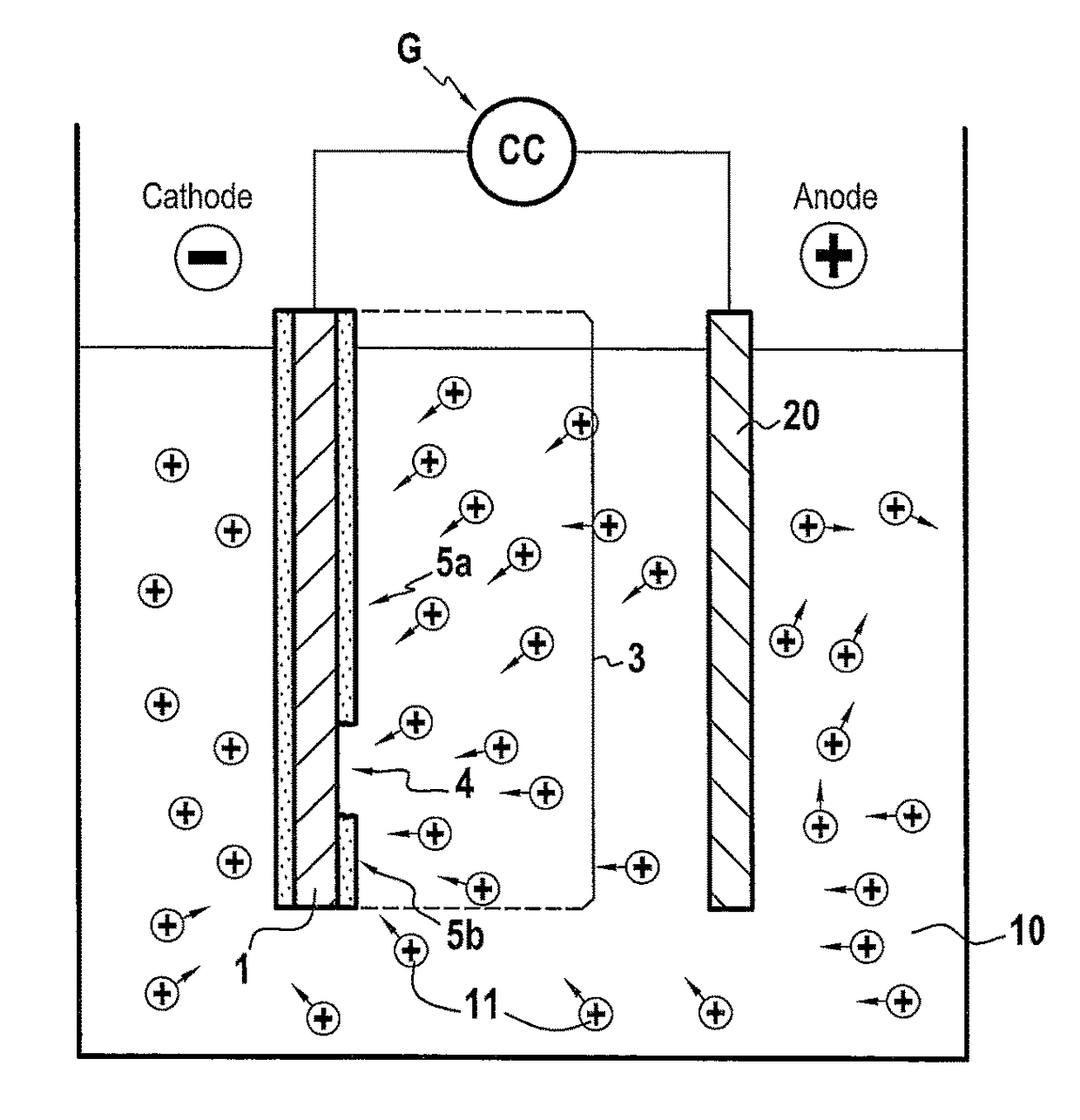
[0012]Advantageously, the invention makes it possible in rapid, inexpensive and localized manner to repair the damaged thermal barrier and thus avoid partially degraded parts being discarded or indeed avoid removing the entire damaged thermal barrier. Consequently, the invention makes it possible to lengthen the lifetime of parts and to limit the cost of putting back into operation parts having a thermal barrier that has been damaged.
[0040]Stripping serves advantageously to eliminate residues of the thermal barrier and of the oxide layers that might be present, and also to improve the electrically conductive nature of the damaged zone that is to be repaired so as to enhance deposition of the ceramic coating by electrophoresis.

Problems solved by technology

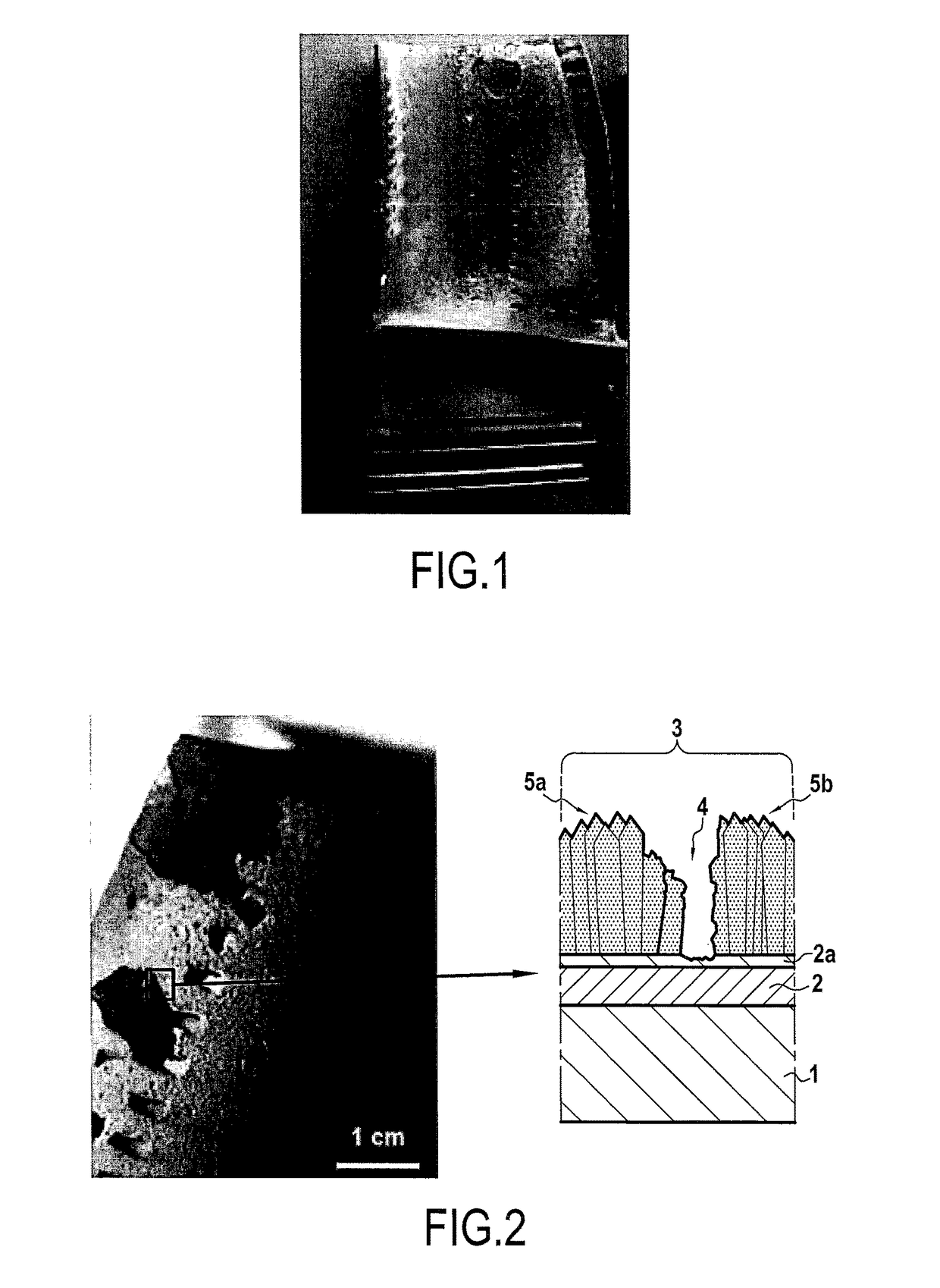
Certain zones of the system may be damaged in service at high temperature by erosion, by particle impact, by oxidation, by corrosion, and by calcium and magnesium aluminosilicates (CMAS).
Such degradation can lead to local disappearance of the thermal barrier layer and even of the underlayer, leading to oxidation of the underlying part.
In certain circumstances, parts having a thermal barrier that has been damaged may even need to be discarded.

Method used


Image

  • Method for localised repair of a damaged thermal barrier
  • Method for localised repair of a damaged thermal barrier
  • Method for localised repair of a damaged thermal barrier

Examples


example

[0071]Use was made of a nickel-based superalloy part coated by an yttria-stabilized zirconia (YSZ) thermal barrier obtained by electron beam physical vapor deposition (ED-PVD). The thermal barrier was initially damaged by water jet. FIG. 4A shows the result obtained after damaging.

[0072]Electrophoresis deposition was performed using a suspension of YSZ powder in isopropanol (10 g / L) at a voltage of 100 V for six minutes. A photograph of the part after treatment by the method of the invention is shown in FIG. 4B.

[0073]It can be seen that a covering and uniform deposit of yttria-stabilized zirconia is obtained throughout the damaged zone.

[0074]The term “comprising / containing a / an” should be understood as “comprising / containing at least one”

[0075]The term “lying in the range . . . to . . . ” should be understood as including the limits of the range.


PUM

PropertyMeasurementUnit
temperaturesaaaaaaaaaa
concentrationaaaaaaaaaa
voltageaaaaaaaaaa

Abstract

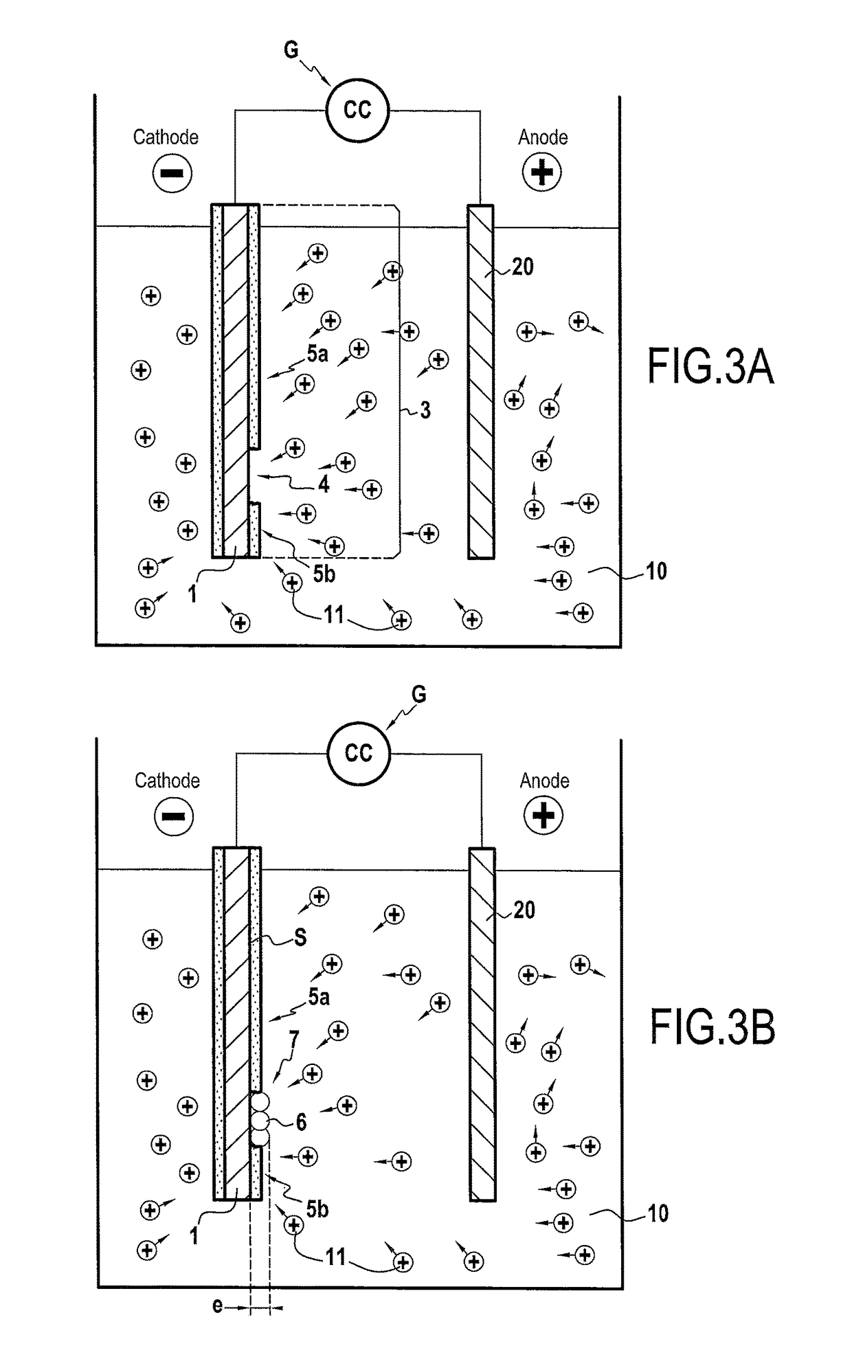
A method of localized repair to a damaged thermal barrier, the method including subjecting a part coated in a damaged thermal barrier to electrophoresis treatment, the part being made of an electrically conductive material, the damaged thermal barrier including a ceramic material and presenting at least one damaged zone that is to be repaired, the part being present in an electrolyte including a suspension of particles in a liquid medium, the ceramic coating being deposited by electrophoresis in the damaged zone in order to obtain a repaired thermal barrier for use at temperatures higher than or equal to 1000° C., the particles being made of a material different from the ceramic material present in the damaged thermal barrier.

Description

CROSS-REFERENCE TO RELATED APPLICATIONS[0001]This is the U.S. National Stage of PCT / FR2014 / 053268, filed Dec. 11, 2014, which in turn claims priority to French Patent Application No. 14 / 00224, filed Jan. 29, 2014, the entire contents of all applications are incorporated herein by reference in their entireties.BACKGROUND OF THE INVENTION[0002]The invention relates to methods of localized repair to damaged thermal barriers.[0003]The blade sets of high-pressure turbines in aeroengines are exposed to an environment that is very aggressive. In general, such parts are coated by an oxidation protection coating and by a thermal barrier coating. The thermal barrier coating serves to insulate the underlying part thermally so as to enable it to be maintained at temperatures where its mechanical performance and its lifetime are acceptable.[0004]Certain zones of the system may be damaged in service at high temperature by erosion, by particle impact, by oxidation, by corrosion, and by calcium and...

Claims


Application Information

Patent Timeline
Patent Type & Authority Patents(United States)
IPC IPC(8): F01D5/00C25D13/20C25D13/12F01D5/28C25D13/22C25D13/02
CPCF01D5/005C25D13/02C25D13/12C25D13/20C25D13/22F01D5/288F05D2300/5023F05D2220/30F05D2230/30F05D2230/40F05D2230/90F05D2300/20C25D13/18
Inventor MALIE, ANDRE HUBERT LOUISHAMADI, SARAHANSART, FLORENCEBONINO, JEAN-PIERRECERDA, HELENEPUJOL, GUILLAUME
Owner SN DETUDE & DE CONSTR DE MOTEURS DAVIATION S N E C M A
Learn More