
Rotary machine comprising a rotor placed in a fluid and equipped with orientable blades

a rotary machine and fluid technology, applied in the direction of motors, climate sustainability, engine fuctions, etc., can solve the problems of unsuitable use, heavy, complicated, etc., and achieve the effect of good yield

Active Publication Date: 2017-12-12
ADV TECH +1
View PDF17 Cites 4 Cited by
  • Summary
  • Abstract
  • Description
  • Claims
  • Application Information

AI Technical Summary

Benefits of technology

The present invention provides a new mechanical solution for controlling the angular servo-control of blades on a rotor, which ensures that the blades follow the rotation of the rotor. The mechanism is simple and adaptable to large diameter rotors, making it suitable for the production of wind turbines in both horizontal and vertical configurations. It can handle violent fluid flows and automatically adjust the maximum pitch of the blades to maintain the rotor mechanism and produce energy in different flow strengths. The rotor diameter can also be adjusted to increase adaptability to the flux strength.

Problems solved by technology

This technical solution is complicated, heavy, power-consuming, and certainly not suitable for use e.g. in the design of a wind turbine.

Method used


Image

  • Rotary machine comprising a rotor placed in a fluid and equipped with orientable blades
  • Rotary machine comprising a rotor placed in a fluid and equipped with orientable blades
  • Rotary machine comprising a rotor placed in a fluid and equipped with orientable blades

Examples


Embodiment Construction

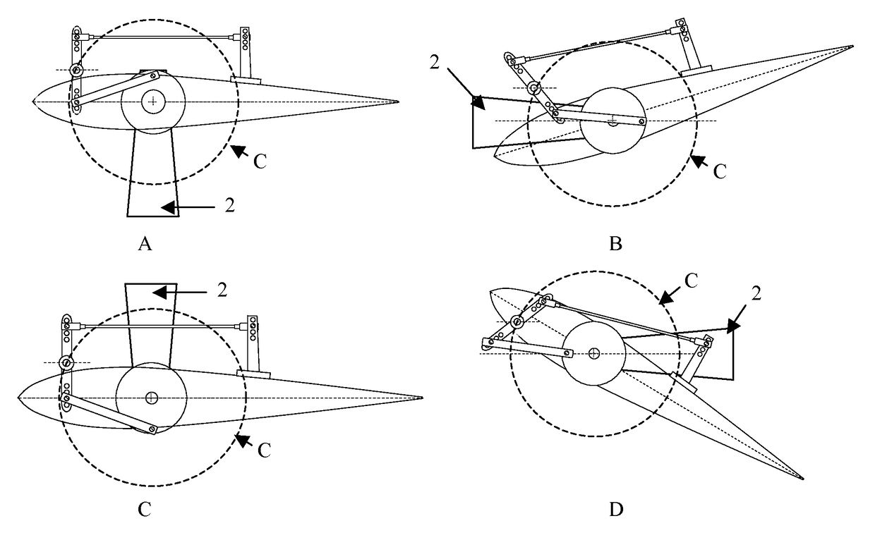
[0043]A fluid-powered machine provided with a mechanism synchronized to the revolution of a rotor arranged in a cross-flow of fluid will now be described, the mechanism allowing controlling the incidence of at least one blade mounted on the periphery of the rotor.

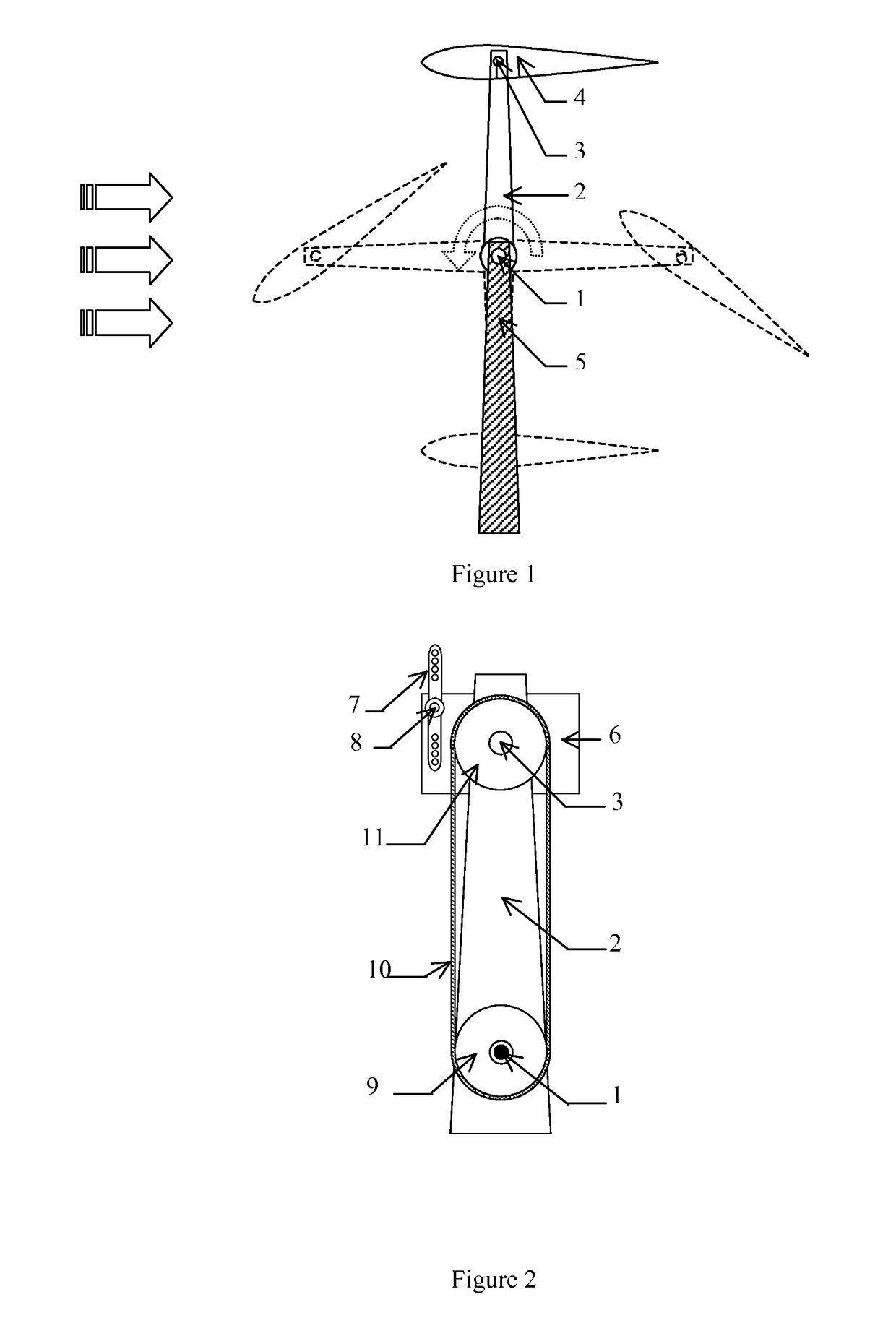
[0044]FIG. 1 shows a general profile view of a one-blade Lipp kinematics type rotor, intended to illustrate the movement of the blade as a function of the angular position of the rotor. The rotor rotates about an axis 1, held by a support structure 5. The blade 4, located at the end of an arm 2, can pivot about axis 3 parallel to axis 1 according a certain cycle and in a range of angles between −90° and +90° relative to the direction of flow, by means of a synchronous mechanism that will now be described.

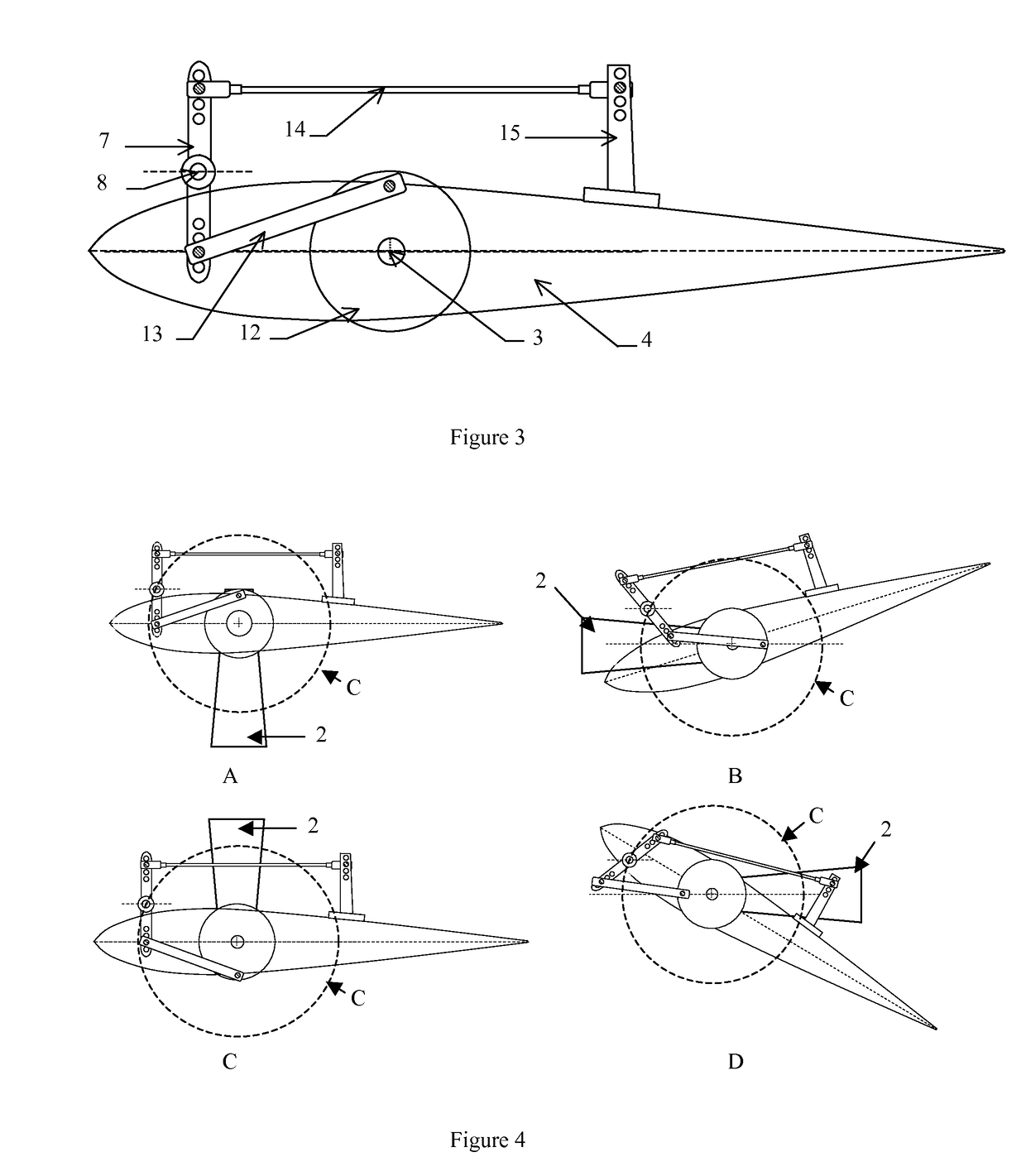
[0045]The first part of the synchronous mechanism is detailed in FIG. 2. This mechanism comprises an eccentric element 6, here called a pod, on which is fixed a pivot 8 around which a deflection element 7 or rudder pivots. ...


PUM


Abstract

A fluidic rotor rotary machine has a rotor comprising at least one blade (4) mounted on an arm (2) rotating about a main axis (1) of the rotor, the rotor being held by a support structure (5) in an orientation such that said axis (1) is essentially perpendicular to the fluid flow direction, the blade (4) being pivotally mounted about a rotational axis (3) parallel to the main axis (1), the machine being characterized in that it comprises means for generating a relative rotational movement of the blade (4) relative to the arm (2) at the rotational axis (3), thereby varying the blade angle, said means comprising an eccentric mechanism rotating on said blade rotational axis.Application in particular to propellers and generators operating according to Lipp-type or Voith-Schneider-type kinematics, with possible mode switching.

Description

TECHNICAL FIELD[0001]The invention relates to generators and propellers working in a transverse fluid flow, and more particularly to a new mechanism for performing the servo control of the inclination of a blade mounted on a rotor as a function to the rotation of the latter.PRIOR ART[0002]According to the prior art, the Lipp rotor is known, and more particularly the mechanism for pitching the blades of a rotor arranged in a transverse fluid flow (see WO9207189A1). The pivot axes of the blades are parallel to the rotor shaft, on the periphery of which they are arranged. Each of them is connected to a toothed pinion in permanent meshing engagement with its intermediate pinion, which itself is in permanent meshing engagement with the central pinion, fixed in absolute terms but off-center relative to the shaft; the pinion remaining free on the other hand.[0003]This rotor is thus made up of blades whose incidence is controlled according to the rotation of the rotor. The mechanical system...

Claims


Application Information

Patent Timeline
Patent Type & Authority Patents(United States)
IPC IPC(8): B63H1/10F03D7/04F03D3/00F03D7/02F03D3/06F03D9/28F03D15/10F03D80/00
CPCF03D3/068B63H1/10F03D3/005F03D7/0224F03D7/04Y02E10/74F05B2260/506F05B2260/72F05B2260/75F05B2260/79
Inventor CURUTCHET, ARNAUDGROSMANGIN, STEPHANEFOURTON, RENAUDCORDE, GABRIEL
Owner ADV TECH
Learn More