Embedded pupil function recovery for fourier ptychographic imaging devices

a fourier ptychographic and embedded pupil technology, applied in the field of imaging techniques, can solve the problems of limited physical resolution of imaging lenses ranging from microscope objectives to satellite-based cameras, interferometric holography has limitations, and constructed images typically suffer from coherent noise, so as to achieve the effect of higher resolution

Active Publication Date: 2018-01-09
CALIFORNIA INST OF TECH
View PDF107 Cites 27 Cited by
  • Summary
  • Abstract
  • Description
  • Claims
  • Application Information

AI Technical Summary

Problems solved by technology

Imaging lenses ranging from microscope objectives to satellite-based cameras are physically limited in the total number of features they can resolve.
These limitations are a function of the point-spread function (PSF) size of the imaging system and the inherent aberrations across its image plane field of view (FOV).
While conventional imaging systems may be able to resolve up to 10 megapixels, there is typically a tradeoff between PSF and FOV.
Interferometric holography has its limitations.
As such, the constructed images typically suffer from coherent noise sources such as speckle noise, fixed pattern noise (induced by diffraction from dust particles and other optical imperfections in the beam path), and multiple interferences between different optical interfaces.
Thus the image quality is typically worse than from a conventional microscope.
On the other hand, using off-axis holography sacrifices spatial-bandwidth product (i.e., reduces total pixel number) of the image sensor.
In addition, interferometric imaging techniques may subject to uncontrollable phase fluctuations between different measurements.
Another limitation is that many of these interferometric imaging systems require mechanical scanning to rotate the sample and thus precise optical alignments, mechanical control at a sub-micron level, and associated maintenances are required by these systems.
Previous lensless microscopy such as in-line holography and contact-imaging microscopy also present drawbacks.
For example, conventional in-line holography does not work well with contiguous samples and contact-imaging microscopy requires a sample to be in close proximity to the sensor.
These complex mechanisms tend to be expensive to fabricate and difficult to use and maintain.

Method used


Image

  • Embedded pupil function recovery for fourier ptychographic imaging devices
  • Embedded pupil function recovery for fourier ptychographic imaging devices
  • Embedded pupil function recovery for fourier ptychographic imaging devices

Examples


Embodiment Construction

[0046]Certain embodiments described herein pertain to Fourier ptychographic imaging systems, devices, and methods.

I. Fourier Ptychographic Imaging Systems

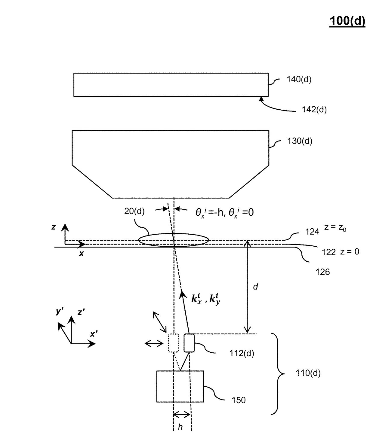
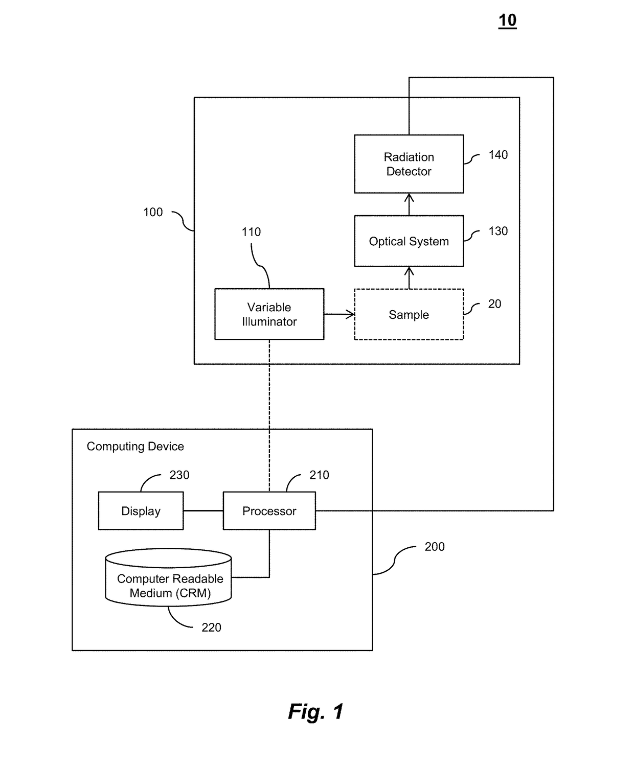
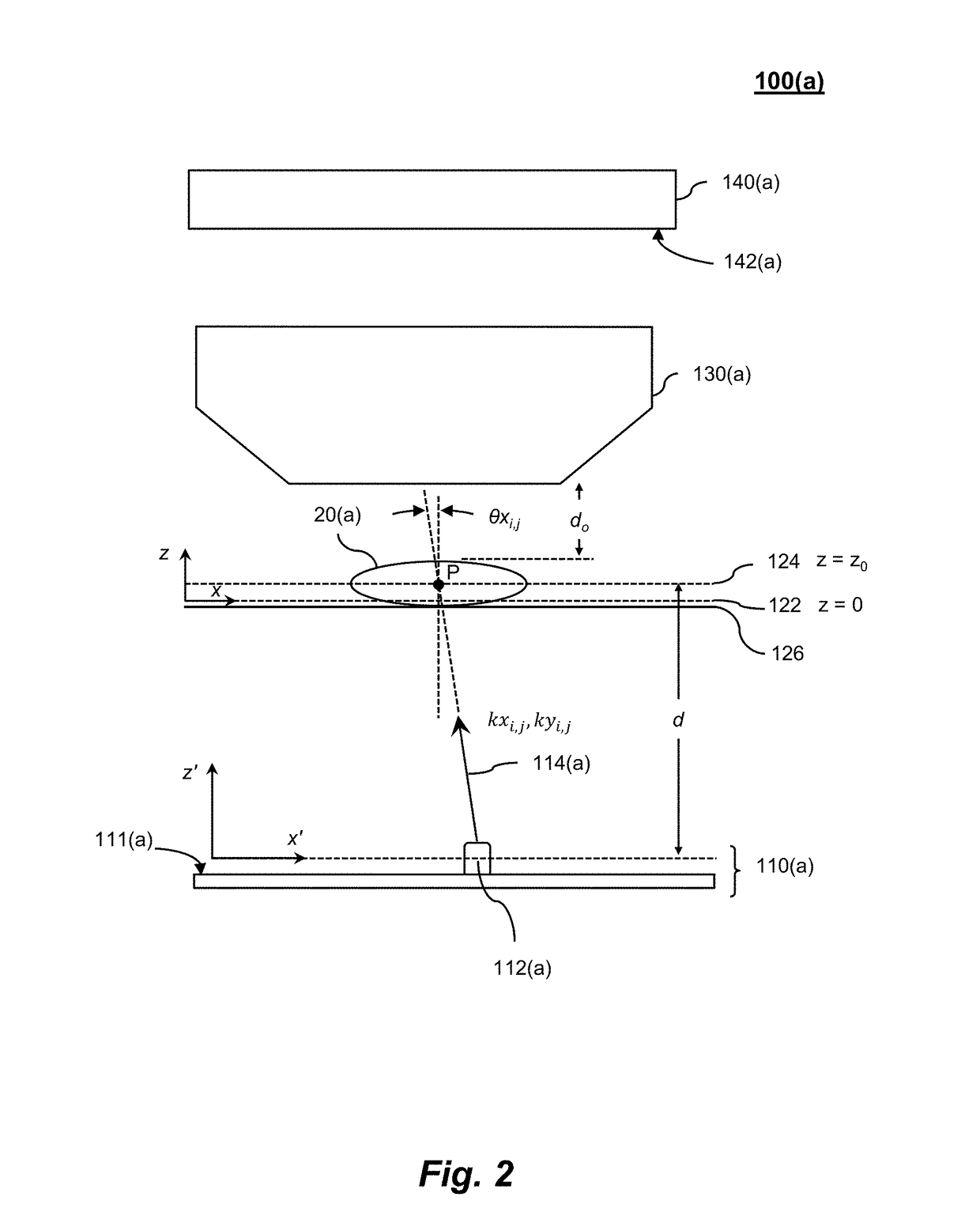
[0047]In certain embodiments, a Fourier ptychographic imaging system comprises a variable illuminator, an optical system, and a radiation detector. In some cases, the Fourier ptychographic imaging system may be in communication with a processor or further comprise a processor (e.g., microprocessor). The variable illuminator can illuminate (e.g., with plane wave illumination) a sample being imaged from a plurality of incidence angles at different sample times. The optical system can receive light issuing from the sample and propagate it to the radiation detector. The optical system comprises at least one filtering optical element that can “filter” light typically based on its acceptance angle. The radiation detector receives light from the optical system, and measures a light intensity distribution for each of the incidence angles t...


PUM


Abstract

Certain aspects pertain to Fourier ptychographic imaging systems, devices, and methods that implement an embedded pupil function recovery.

Description

CROSS-REFERENCES TO RELATED APPLICATIONS[0001]This application is a continuation-in-part application of U.S. patent application Ser. No. 14 / 065,280, titled “FOURIER PTYCHOGRAPHIC IMAGING SYSTEMS, DEVICES, AND METHODS,” filed on Oct. 28, 2013, which claims priority to U.S. Provisional Patent Application No. 61 / 720,258 entitled “Breaking the Spatial Product Barrier via Non-Interferometric Aperture-Synthesizing Microscopy (NAM),” filed on Oct. 30, 2012 and to U.S. Provisional Patent Application No. 61 / 847,472 entitled “Fourier Ptychographic Microscopy,” filed on Jul. 17, 2013. This application is also a continuation-in-part application of U.S. patent application Ser. No. 14 / 466,481 titled “VARIABLE-ILLUMINATION FOURIER PTYCHOGRAPHIC IMAGING DEVICES, SYSTEMS, AND METHODS,” filed on Aug. 22, 2014, which claims priority to U.S. Provisional Patent Application No. 61 / 899,715, titled “Increasing Numerical Aperture of Dry Objective to Unity via Fourier Ptychographic Microscopy” and filed on N...

Claims


Application Information

Patent Timeline
Patent Type & Authority Patents(United States)
IPC IPC(8): G01B9/02G02B21/00G02B21/36G02B27/58G21K7/00G06K9/00
CPCG02B21/367G02B21/002G21K7/00G02B27/58G06K9/00134G02B21/365G06V20/693
Inventor OU, XIAOZECHUNG, JAEBUMHORSTMEYER, ROARKEZHENG, GUOANYANG, CHANGHUEI
Owner CALIFORNIA INST OF TECH
Why Eureka
Try Eureka