Oil-immersion enhanced imaging flow cytometer

a flow cytometer and oil immersion technology, applied in the field of enhanced optical flow imaging and analysis configuration, can solve the problems of less-than-optimal collection of image illumination energy from the sample, inefficiency of optically imaging with air microscope objectives, and mediocre resolution, and achieve the effect of improving the durability of flow cells and immersion oil retention

Active Publication Date: 2018-02-13
YOKOGAWA FLUID IMAGING TECH INC
View PDF3 Cites 4 Cited by
  • Summary
  • Abstract
  • Description
  • Claims
  • Application Information

AI Technical Summary

Benefits of technology

[0006]It is an object of the present invention to provide an improved imaging flow cytometer with better flow cell durability and immersion oil retention. It is also an object of the present invention to provide such a flow cell that may be incorporated into, or operate in a similar manner as that of, existing imaging flow cytometers including, for example, the flow cytometer described in U.S. Pat. No. 7,796,256. These and other objects are achieved with the present invention, which includes a more durable flow cell and the introduction of configured stiffening wires adjacent to the sidewalls of the flow cell, which sidewalls are not used for particle analysis.

Problems solved by technology

The inefficiencies of optically imaging with air microscope objectives into and out of the flow cell may include a mediocre resolution, less-than-optimum collection of the image illumination energy from the sample, less than optimum illumination of the sample with fluorescence excitation light and less than optimum collection of fluorescence emissions from the sample.
However, the system described in the U.S. Pat. No. 7,796,256 utilizes an extremely fragile flow cell, which can fracture due to the slightest pressure on the glass.
With this configuration, it is also difficult to keep the immersion oil from dripping out from between the flow cell and the objective and condenser lenses.

Method used


Image

  • Oil-immersion enhanced imaging flow cytometer
  • Oil-immersion enhanced imaging flow cytometer
  • Oil-immersion enhanced imaging flow cytometer

Examples


Embodiment Construction

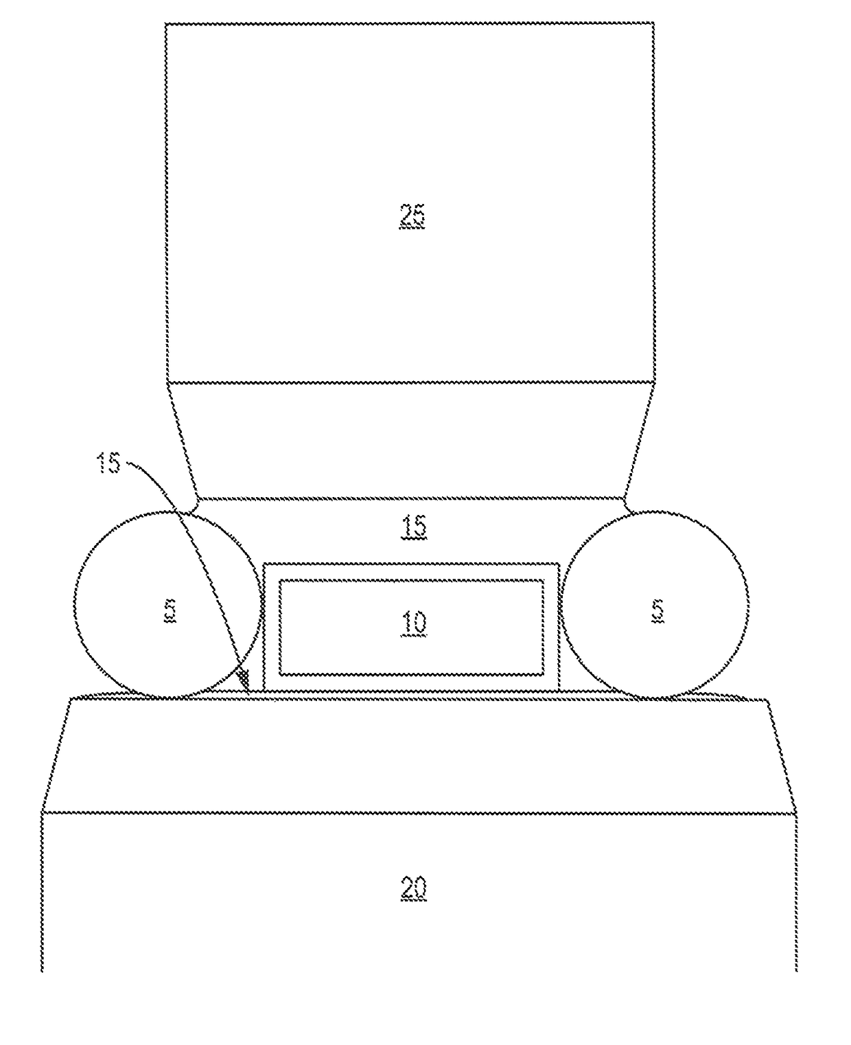
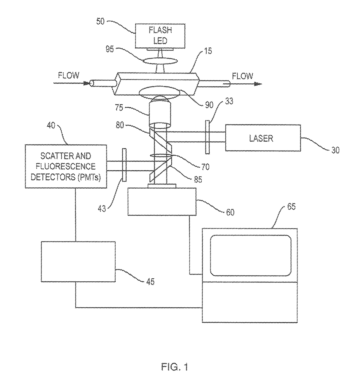
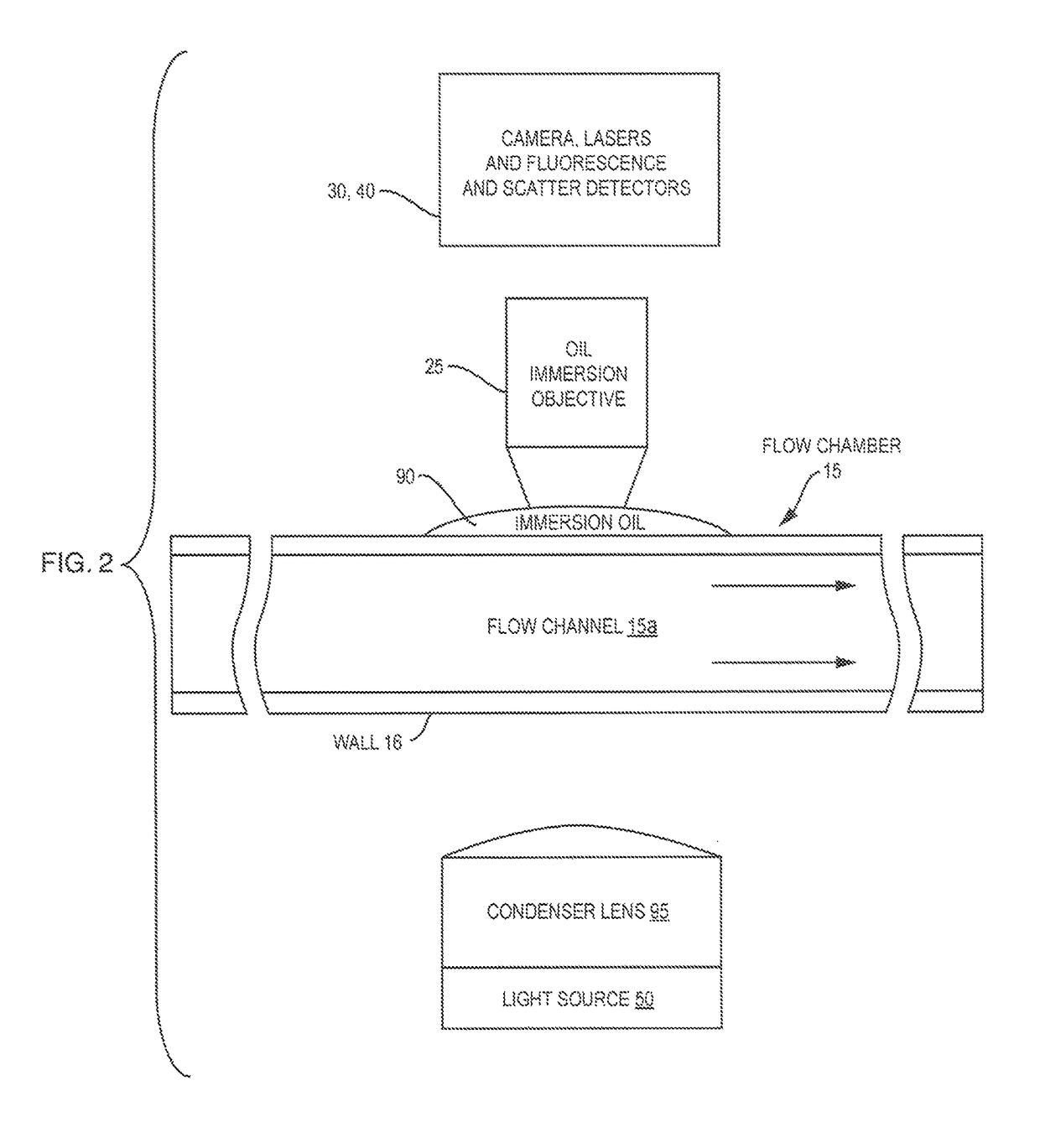
[0014]A system 10 of the present invention suitable for high quality automated counting and imaging of particles that exist in a fluid is shown in FIGS. 1 and 2. The system 10 includes a flow chamber 15, a light source 30, optics 35, an image detection system 40, a backlighting generator 50, an image capturing system 60, a computing device 65, a high NA objective 75, an immersion oil 90, and a high NA condenser lens 95. The combination of these components of the system 10 arranged and configured as described herein enable a user to detect particles in the fluid and produce high resolution images of those particles in a manner not enabled by existing flow cytometers.

[0015]The flow chamber 15 includes an inlet 20 for receiving the particle-containing fluid to be observed, and an outlet 25 through which the fluid passes out of the flow chamber 15 after imaging functions have been performed. The flow chamber 15 is a low fluorescence structure. That is, it may be fabricated of a material...


PUM

PropertyMeasurementUnit
wavelengthaaaaaaaaaa
refractive indexaaaaaaaaaa

Abstract

A flow chamber, imaging objective, condenser and imaging light source as part of an optical system includes an oil-immersion objective and high numerical aperture condenser matched to a rectangular flow chamber. The oil-immersion objective and flow chamber include a high index of refraction immersion oil so as to enhance the optical resolution and optical coupling therethrough. The flow chamber is reinforced with stiffening wires that are arranged to extend above a surface of the sidewalls of the flow chamber so as to function as a barrier to leakage of the immersion oil away from the surface of the flow chamber.

Description

BACKGROUND OF THE INVENTION1. Field of the Invention[0001]The present invention relates generally to the enhancement of an optical flow imaging and analysis configuration used in particle analysis instrumentation, and more particularly to the enhancement of a high numerical aperture optical flow imaging system incorporating a flow chamber, immersion oil and high numerical aperture optics, including a high numerical aperture oil-immersion objective.2. Description of the Prior Art[0002]The art has seen various optical / flow systems employed for transporting a fluid within an analytical instrument to an imaging and optical analysis area. A liquid sample is typically delivered into the bore of a flow chamber and this sample is interrogated in some way so as to generate analytical information concerning the nature or properties of the sample. For example, a laser beam may excite the sample that is present in the bore of the capillary, with the emitted fluorescence energy representing the ...

Claims


Application Information

Patent Timeline
Patent Type & Authority Patents(United States)
IPC IPC(8): G01N15/14G01N21/64G01N33/28
CPCG01N15/1459G01N15/1436G01N21/6456G01N33/2835G01N2201/06113G01N15/147G01N2015/1452G02B21/0088G02B21/33
Inventor SIERACKI, CHRISTIAN K.PETERSON, KENT A.
Owner YOKOGAWA FLUID IMAGING TECH INC
Why Eureka
Try Eureka