Layered or mixed sorbent bed protective filtration device

a protective filtration device and sorbent bed technology, applied in the field of filter media, can solve the problems and achieve the effect of limiting the overall weight of the canister/filter assembly and the leverage it may exert on the user's neck muscles

Inactive Publication Date: 2018-04-03
UNITED STATES OF AMERICA +1
View PDF44 Cites 1 Cited by
  • Summary
  • Abstract
  • Description
  • Claims
  • Application Information

AI Technical Summary

Benefits of technology

[0007]It would be highly desirable to improve the performance of current industrial replaceable canister / filter assemblies with respect to the protection provided against target gases. Although the applicable standards are in many cases performance standards rather than design standards, nonetheless it is desirable to minimize the overall canister / filter volume and depth. Doing so helps preserve a user's field of view and limits the overall canister / filter assembly weight and the leverage it may exert on the user's neck muscles when worn.
[0016]The disclosed filtration device and method may be used for personal or collective protection. For example, the disclosed method may be used to fabricate personal respiratory protection devices (including passive air purifying or nonpowered respirators, as well as powered air respirators), and to fabricate collective protection devices (including HVAC filters and vehicle filters) for buildings, vehicles and other places where people reside, work or gather. The disclosed filtration device and method provide particularly useful improvements in breakthrough times for nitrogen dioxide, hydrogen sulfide, ammonia and formaldehyde. In a preferred embodiment, the replaceable canister / filter breakthrough times for nitrogen dioxide, hydrogen sulfide and formaldehyde are synergistically improved compared to the observed breakthrough times for a canister / filter having the same internal volume but filled only with the first filter media particles or filled only with the second filter media particles.

Problems solved by technology

Doing so helps preserve a user's field of view and limits the overall canister / filter assembly weight and the leverage it may exert on the user's neck muscles when worn.

Method used


Image

  • Layered or mixed sorbent bed protective filtration device
  • Layered or mixed sorbent bed protective filtration device
  • Layered or mixed sorbent bed protective filtration device

Examples


example 1

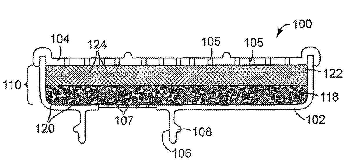
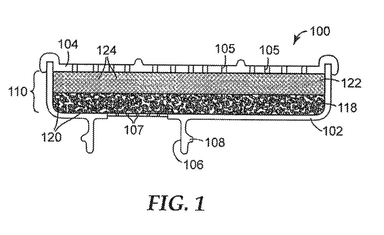
[0070]Unfilled two-piece housings for canister / filter cartridges of the type used on the 3M™ 6200 Half Facepiece Reusable Respirator (3M Company) were filled with filter media particles as described below. The cartridge housings had a 105 cm3 internal volume in which filter media particles could be compressed. A first porous scrim was inserted in each housing bottom, followed by addition via snowstorm filling of a layered filter media particle bed or beds as shown below in Table 1. Run No. 1 employed a single filter bed made entirely from CALGON URC 20×40 impregnated carbon particles from Calgon Carbon Corporation. The particles had been treated with 3 wt. % TEDA using sublimation like that employed for Filter Media Particles #3 in Example 1 of the above-mentioned Smith et al. patent. The TEDA treatment could have been omitted, as it was not needed to address the gases tested below. Run No. 2 employed a single filter bed made entirely from “ZZ” 20×40 zirconium hydroxide / zinc oxide p...


PUM

PropertyMeasurementUnit
particle diametersaaaaaaaaaa
diameteraaaaaaaaaa

Abstract

A filtration device including a fluid-impermeable housing having a gas inlet and outlet, and containing within the housing first filter media particles of an extended surface area substrate and containing at least one metal impregnant, and second filter media particles of an extended surface area zirconium hydroxide substrate and zinc (hydr)oxide. The device may be used in atmospheres containing various harmful gases, and may provide particularly useful improvements in NOx breakthrough times compared to a device containing only the first filter media particles or only the second filter media particles.

Description

GOVERNMENT INTEREST[0001]The invention described herein may be manufactured, used, and / or licensed by or for the Government of the United States.TECHNICAL FIELD[0002]This invention relates to filter media used to remove contaminants from respiratory air.BACKGROUND[0003]Extended surface area substrate particles, such as activated carbon, alumina, zeolites, and the like, are widely used in air filtration because of their ability to remove a wide range of contaminants from the air. The highly porous structure of these materials provides a high surface area that is very suitable for filtration purposes. In the case of activated carbon, the porosity results from controlled oxidation during the “activation” stage of manufacture.[0004]The ability of such carbon to remove contaminants from air generally involves direct absorption and depends on molecular-scale interactions between a gaseous molecule and the carbon surface. The extent of this interaction may depend upon factors including the...

Claims


Application Information

Patent Timeline
Patent Type & Authority Patents(United States)
IPC IPC(8): A62B19/00B01D53/04B01J20/06B01D39/20B01J20/28B01J20/32A62B7/10A62B23/02B01D53/82B01D53/02
CPCB01D53/0407A62B23/02B01D39/2058B01D39/2072B01D53/02B01D53/82B01J20/06B01J20/28052B01J20/3204B01J20/3236A62B7/10B01J2220/56A62B19/00B01D2251/604B01D2253/102B01D2253/112B01D2253/1122B01D2253/25B01D2257/302B01D2257/404B01D2257/406B01D2258/06B01D2259/4143B01D2259/4146B01D2259/4541B01D27/02B01D27/148B01D39/2031B01D46/0001B01D46/64
Inventor BILLINGSLEY, BRITTON G.BREY, LARRY A.BUECHTER, WILLIAMLEGARE, PIERREMAANUM, DEREK M.PETERSON, GREGORY W.ROSSIN, JOSEPH A.
Owner UNITED STATES OF AMERICA
Why Eureka
Try Eureka