Control of alternator with front end accessory drive

a technology of accessory drive and alternator, which is applied in the direction of electric generator control, engine starters, magnetic circuit shape/form/construction, etc., can solve the problems of less efficient alternator operation, less efficient alternator electrical output, and at times insufficient alternator electrical output to supply electrical load, so as to reduce vehicle fuel efficiency, less efficient, and increase vehicle mass

Active Publication Date: 2018-04-03
FORD GLOBAL TECH LLC
View PDF17 Cites 0 Cited by
  • Summary
  • Abstract
  • Description
  • Claims
  • Application Information

AI Technical Summary

Benefits of technology

[0002]A vehicle may include an alternator for converting mechanical energy into electrical energy. The electrical energy produced by the alternator may be stored in an electrical energy storage device for future consumption or the electrical energy may be consumed by electrically powered devices as the electrical energy is produced. Recently, electrical loads within the vehicle have increased and are expected to increase further as autonomous vehicles are put into production. For example, some vehicles include electrically assisted steering and electrically driven climate control systems. Autonomous vehicles may include object and distance observing sensors as well as enhanced communications systems and actuators to position, stop, and accelerate the vehicle. The electrical loads may increase well beyond that which a medium duty alternator may provide. Further, a speed of an engine driving the alternator may vary such that the engine drives the alternator at speeds where the alternator operates less efficient than may be desired. Further still, the engine speed may operate front end accessory devices (FEAD) at speeds that may be less efficient. Consequently, the alternator electrical output may be at times insufficient to supply the electrical load unless the alternator is sized large and FEAD devices may be less efficient than is desired. However, increasing the alternator size may increase vehicle mass, thereby decreasing vehicle fuel efficiency. Further, installing a clutch between FEAD accessories and the engine may decrease driveline efficiency. As such, it would be desirable to provide an alternator that has high output capacity with a reduced mass and a variable speed FEAD driving device.
[0004]By adjusting current supplied to a second field winding of an electrical machine providing electrical energy to electrical consumers, it may be possible to provide the technical result of providing improved front end accessory drive speed control. For example, if engine output increases, current supplied to a field of an alternator may be increased to increase water pump speed or speed of other front end accessory devices (FEAD). In this way, water pump output may be increased to provide additional cooling even if engine speed is constant.
[0005]The present description may provide several advantages. In particular, the electric machine may improve FEAD device speed control. Further, driveline efficiency may be improved by operating FEAD devises in a desired speed range while engine speed changes. Further still, the mechanical output and electrical output of the electric machine may be tailored to improve vehicle driveline efficiency.

Problems solved by technology

Further, a speed of an engine driving the alternator may vary such that the engine drives the alternator at speeds where the alternator operates less efficient than may be desired.
Further still, the engine speed may operate front end accessory devices (FEAD) at speeds that may be less efficient.
Consequently, the alternator electrical output may be at times insufficient to supply the electrical load unless the alternator is sized large and FEAD devices may be less efficient than is desired.
However, increasing the alternator size may increase vehicle mass, thereby decreasing vehicle fuel efficiency.
Further, installing a clutch between FEAD accessories and the engine may decrease driveline efficiency.

Method used


Image

  • Control of alternator with front end accessory drive
  • Control of alternator with front end accessory drive
  • Control of alternator with front end accessory drive

Examples


Embodiment Construction

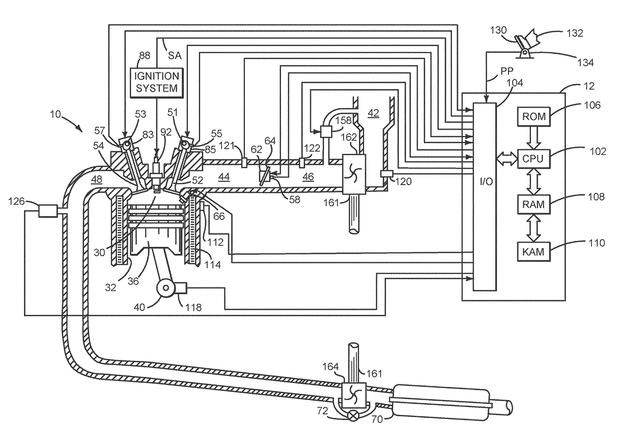
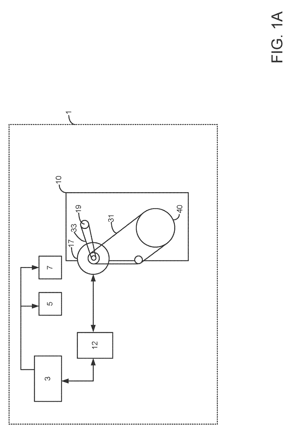
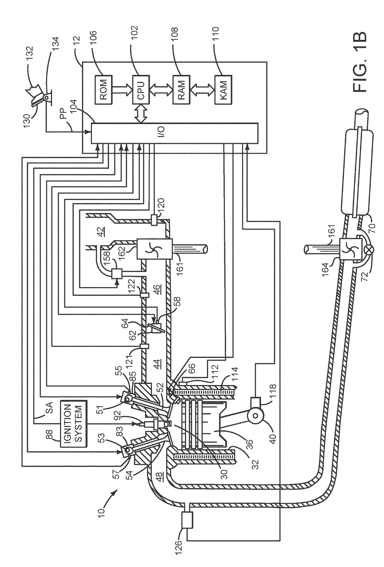
[0013]The present description is related to an electric machine. The electric machine may be operated as an alternator or as a starter. The electric machine may be incorporated into a vehicle powertrain as is shown in FIGS. 1A and 1B. The alternator / starter may be configured as is shown in FIGS. 2A-4C. The alternator / starter may be operated as is shown in FIG. 5 according to the method shown in FIG. 6.

[0014]Referring to FIG. 1A, a schematic diagram of an alternator / starter in a vehicle system is shown. Vehicle 1 includes an engine 10, a controller 12, an electric energy storage device 3, and electrical power consumers 5 and 7. Electrical power consumers may include navigation systems as well as electric braking actuators, electric steering actuators, object and distance sensing devices, engine torque actuators such as electrically operated throttles, engine cooling fans, electric water pumps, heat pump compressors, and vehicle climate control systems.

[0015]Alternator / starter 17 is m...


PUM


Abstract

Control of alternator / starters for providing electrical power to a vehicle and rotating an engine is disclosed. In one example, the alternator / starter provides a differential action whereby torque on an input side of the alternator may be maintained while speed of an output side of the alternator may be varied. The alternator / starter includes two armature windings and two field windings.

Description

FIELD[0001]The present description relates to systems and methods for a vehicle alternator or generator. The methods may be particularly useful for compound alternators that provide electrical power to vehicle electrical loads and transfer rotational energy from an engine to mechanically driven accessory devices.BACKGROUND AND SUMMARY[0002]A vehicle may include an alternator for converting mechanical energy into electrical energy. The electrical energy produced by the alternator may be stored in an electrical energy storage device for future consumption or the electrical energy may be consumed by electrically powered devices as the electrical energy is produced. Recently, electrical loads within the vehicle have increased and are expected to increase further as autonomous vehicles are put into production. For example, some vehicles include electrically assisted steering and electrically driven climate control systems. Autonomous vehicles may include object and distance observing sen...

Claims


Application Information

Patent Timeline
Patent Type & Authority Patents(United States)
IPC IPC(8): H02P9/00H02P9/14H02K1/06H02K16/00H02P7/18H02K51/00H02K7/18
CPCH02P9/14H02K1/06H02K51/00H02P7/18H02K16/00H02K7/1815B60R16/03H02K27/20H02P25/18F02N11/04F02N19/00H02P9/007H02P9/30H02P25/16
Inventor ELIE, LARRY DEAN
Owner FORD GLOBAL TECH LLC
Why Eureka
Try Eureka