Systems and methods for generating electric power with an electric motor

a technology of electric motors and electric motors, applied in the field of generators, can solve the problems of limiting the ability to have a more productive life, reducing the efficiency of electric motors, so as to ensure the safety of the population, supply more electricity than it consumes, and small size

Active Publication Date: 2018-04-10
COODY CHRIS
View PDF15 Cites 0 Cited by
  • Summary
  • Abstract
  • Description
  • Claims
  • Application Information

AI Technical Summary

Benefits of technology

[0007]In view of the foregoing, the present invention discloses an improved electric generator derived through a unique method of magnetic field manipulation. This improved generator design which, because of its small size and design features for supplying more electricity than it consumes during operation, provides an electric generator that allows the owner to be independent of any outside fuel source or power supply and allows them to carry their power source with them and to occupy remote or desolate areas. It would also allow a user to no longer be dependent on a supply of gas or diesel when combined with an electric motor for a car. This has huge implications when extended to maritime situations, military uses, oil and gas use, and even space travel. The present invention further discloses a way to safeguard the population by eliminating the reliance on the current power grid and thus eliminating a potential national security risk if an EMP were to be used by some hostile element. The present invention discloses a method for producing a generator that, through the use of an improved design, allows the use of generators in confined spaces.

Problems solved by technology

The inability to supply a consistent source of electricity has restricted the ability to have a more productive life in many Third World countries because of the lack of dependable lighting for schools and hospitals, refrigeration, water pumps, etc.
Hydro-generation is more reliable, but restricted to a powerful and consistent water source such as a dam or stable river.
The above-mentioned sources have trouble supplying a consistent amount of power due to cloudy days for solar, no or low wind days for wind power, flooding rivers or drought for hydro power, and the difficulty of supplying gas or diesel in remote areas for generators with an internal combustion engine.
However, the system is fragile and susceptible to attack from an EMP (electromagnetic pulse) delivered by a terrorist organization or a strong solar discharge such as the Carrington Event in 1859, which could destroy our electrical system today.
The grid is also in danger of failure because of the age of the system and the strain that an ever-increasing population is putting on it.
Another major problem with power plants is the amount of pollution released in the form of CO2 emissions from coal and gas plants and the danger that a core meltdown could provide with a nuclear plant, such as the Fukushima, Three Mile Island, or Chernobyl power plants.
Our World cannot afford another Fukushima and there is great concern that the burning of fossil fuels adds to Global Warming.
Despite all the benefits from improved electric generator designs, Applicant is unaware of any designs that meet these requirements.
The misunderstanding of the relationship of copper coils, such as in a rotor, and the magnetic fields that can be generated in them with an electric current has prevented any individual from fully utilizing them until now.

Method used


Image

  • Systems and methods for generating electric power with an electric motor
  • Systems and methods for generating electric power with an electric motor
  • Systems and methods for generating electric power with an electric motor

Examples


Embodiment Construction

[0031]The benefits provided by embodiments of the generator include improved methods of manipulating magnetic fields for power generation. In some embodiments, a common AC or universal motor is modified to function as a generator connected to a power source, such as a battery.

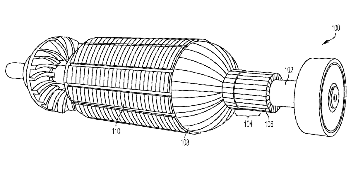
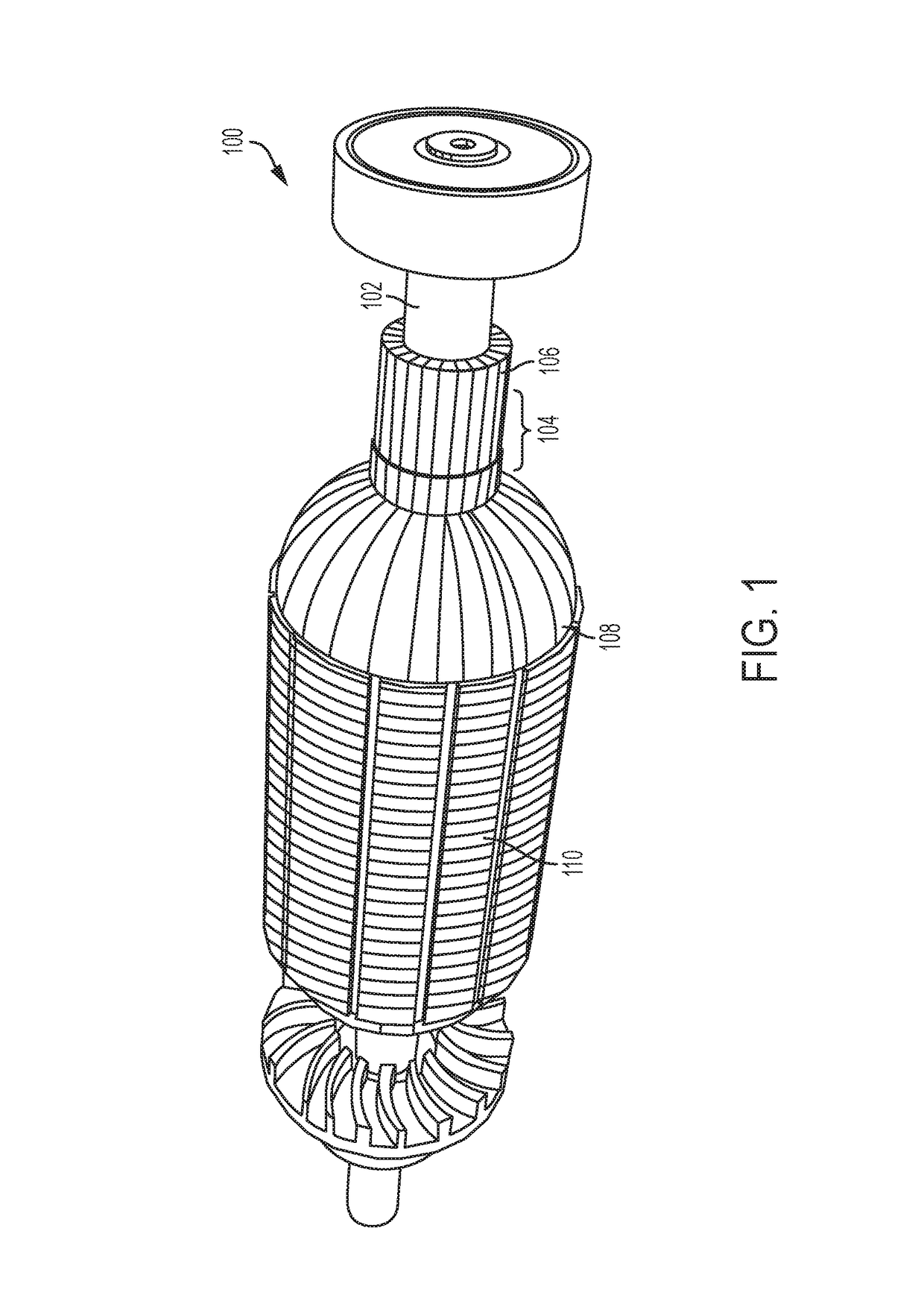
[0032]In some embodiments, the generator may use a traditional rotor that is used in electric motors, such as a treadmill, electric saw, or grinder. FIG. 1 illustrates a common rotor 100 with a shaft 102 that is designed to rotate around a longitudinal axis that runs down the center of the shaft 102. The rotor 100 may rotate in a clockwise or counter-clockwise direction. A commutator 104 surrounds the shaft 102 and consists of a number of strips or contacts 106 for connection to a power source. The rotor 100 also includes coils / windings 108 that comprise copper wiring that is wound throughout a portion of the length of the rotor 102. Generally, coils / windings 108 may be copper wires that are laid in coils usual...


PUM


Abstract

The present invention uses a traditional electrical motor with a rotor to generate electricity or power. By manipulating the magnetic fields within a rotor, large amounts of electricity are generated by the rotation of the rotor within an external magnetic field. Oppositely charged rare-earth magnets are placed around the rotor to create a strong magnetic field that the rotor can spin or rotate within. A battery or other power source supplies power to the rotor at positive and negative terminals (brushes) that are connected to commutator. The positive and negative terminals contact the commutator close to each other, such that only a few windings or coils are charged or magnetized, and the remaining windings or coils are free to generate electricity within the external magnetic field. The few coils that are charged in combination with the external magnetic fields create sufficient rotation, while enabling the remaining “free” coils to generate electric power. This power or electricity that is generated is then collected at a terminal about 150-200 degrees from the positive and negative terminals from the power source. The rotor may be offset or closer to one set of magnets, which further improves power generation.

Description

TECHNICAL FIELD[0001]The present invention relates generally to electrical power generation and, more specifically, to a generator that uses an electric motor to generate electricity.BACKGROUND OF THE INVENTION[0002]Many devices have been invented since the mid 1800s to utilize the electric current generated from moving a copper coil in a magnetic field. This relationship, whether in an alternator, electric motor, or generator has become a staple of our life today, especially in First and Second World countries. The inability to supply a consistent source of electricity has restricted the ability to have a more productive life in many Third World countries because of the lack of dependable lighting for schools and hospitals, refrigeration, water pumps, etc. Until now, power generation required the use of some force, such as that provided by an internal combustion engine, whether it be gas or diesel, or some less reliable source such as solar or wind power, to turn a generator. Hydro...

Claims


Application Information

Patent Timeline
Patent Type & Authority Patents(United States)
IPC IPC(8): H02K13/00H01R39/60H02K47/16H02K53/00
CPCH01R39/60H02K47/16Y10S74/09H02K53/00H02K23/66
Inventor COODY, CHRISDEL VALLE ALONSO, BORIS
Owner COODY CHRIS
Why Eureka
Try Eureka