
Method and apparatus for direct conversion receiver correcting direct current offset

a direct conversion receiver and direct current offset technology, applied in the direction of dc level restoring means or bias distort correction, line balance variation compensation, baseband system details, etc., can solve the problems of reducing affecting the reception of signals, so as to prevent the degradation of the performance of the receiver and the effect of reducing the direct current offs

Active Publication Date: 2018-04-17
SAMSUNG ELECTRONICS CO LTD
View PDF44 Cites 3 Cited by
  • Summary
  • Abstract
  • Description
  • Claims
  • Application Information

AI Technical Summary

Benefits of technology

The invention aims to minimize the offset voltage in a receiver by controlling the current in the variable digital to analog converters (DACs) and calibrating it based on the determined current control code. This helps in accurately cancling out the offset voltage, preventing performance degradation of the receiver due to external factors like signal modulation method and heat. In simpler terms, the invention ensures that the receiver remains free from unwanted voltage levels, resulting in improved performance.

Problems solved by technology

However, as the DC offset increases, a performance of the receiver lowers.
In a severe case, it can be difficult to receive a signal.
However, such a method has a disadvantage of causing signal attenuation according to a modulation method or a cutoff frequency of the pass filter and thus degrading the performance of the receiver.

Method used


Image

  • Method and apparatus for direct conversion receiver correcting direct current offset
  • Method and apparatus for direct conversion receiver correcting direct current offset
  • Method and apparatus for direct conversion receiver correcting direct current offset

Examples


Embodiment Construction

[0020]Preferred embodiments of the present invention will now be described with reference to the accompanying drawings. In descriptions of the present invention, when specific description of well-known functions or configuration is determined to unnecessarily obscure the subject matter of the present invention, its detailed description shall be omitted. Further, terms described below are defined in consideration of functions of the present invention, and can vary according to a user, an operator's intention, or practice. Therefore, the definition should be made based on descriptions throughout the specification.

[0021]In various embodiments of the present invention, an expression such as “have”, “can have”, “include” or “can include” refers to presence such as a corresponding function, operation, or component of the disclosure, and does not limit additional one or more functions, operations, or components. In addition, in various embodiments of the present invention, a term such as “...


PUM


Abstract

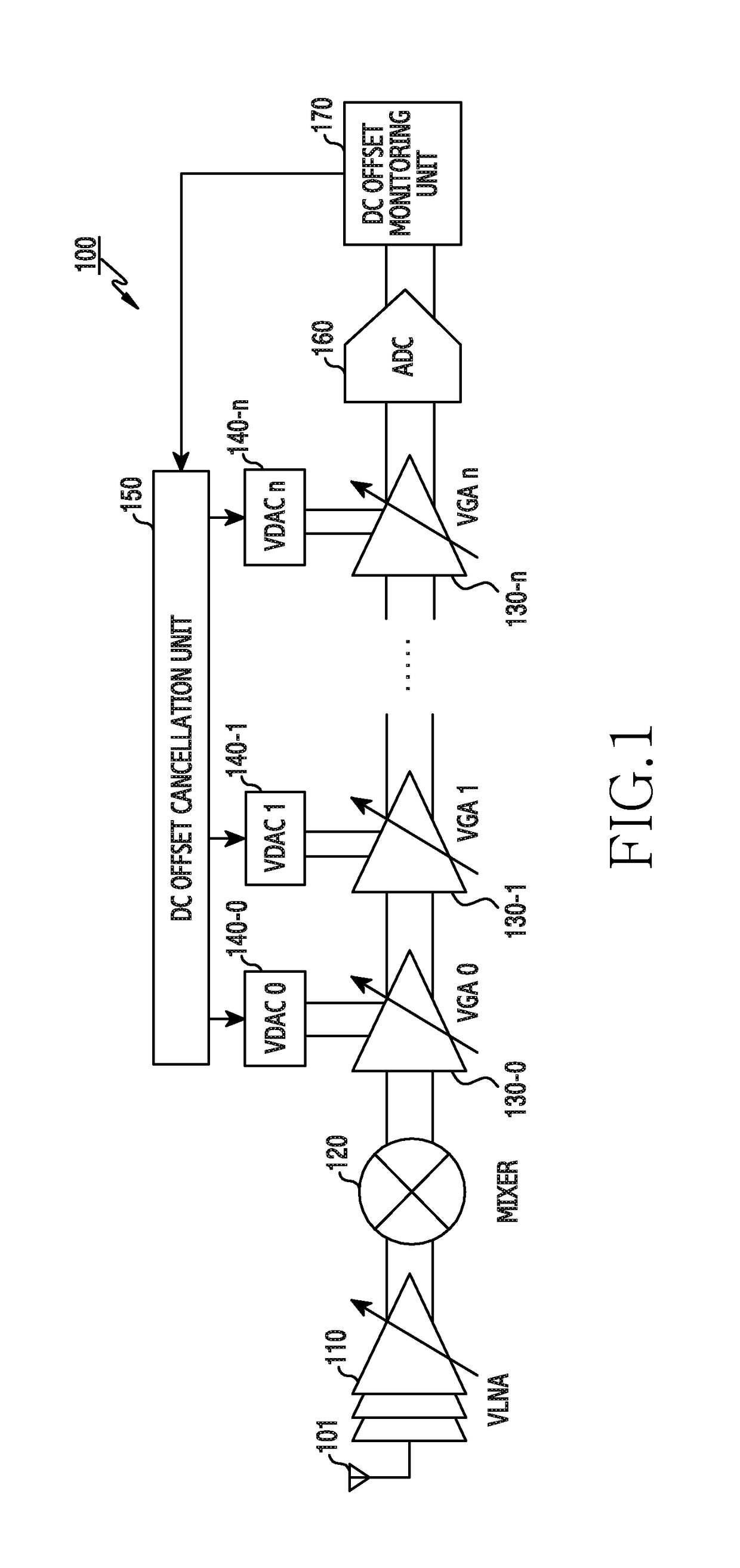
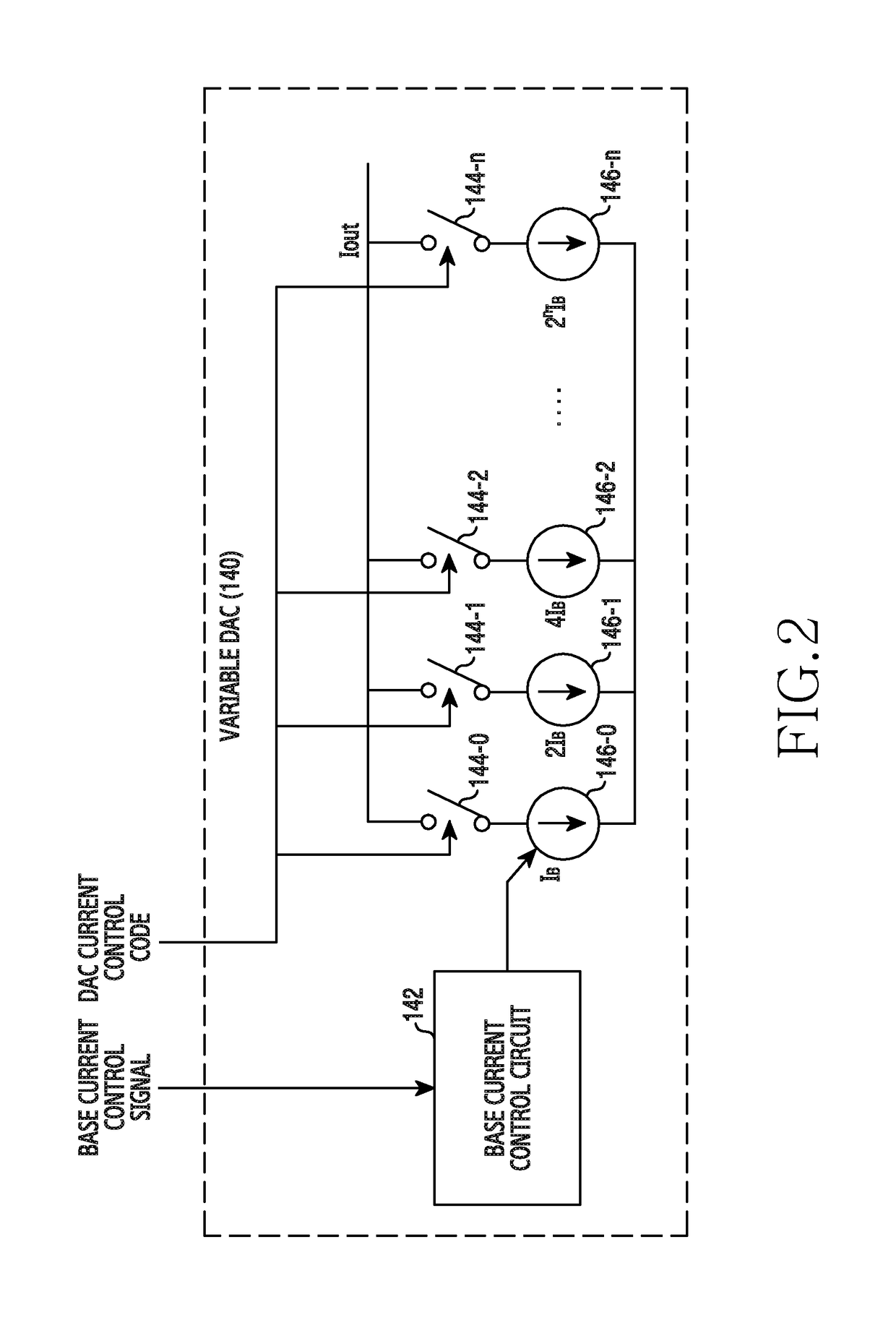
The present invention relates to a method and an apparatus for direct current offset calibration of a direct conversion receiver, a Direct Current (DC) offset calibration apparatus of a direct conversion receiver includes a plurality of variable gain amplifiers for amplifying an input signal based on a gain control value, a DC offset monitoring unit for monitoring a DC offset for an output signal of the plurality of variable gain amplifiers, a plurality of variable Digital to Analog Converters (DACs) for controlling a current applied to each of the plurality of variable gain amplifiers according to a current control code, and a DC offset cancellation unit for determining a current control code set which minimizes the DC offset value per preset gain control value, and thus the DC offset can be precisely cancelled without being affected by external factors such as a signal modulation method and heat and performance degradation of the receiver can be prevented.

Description

TECHNICAL FIELD[0001]The present invention relates generally to a method and an apparatus for calibrating a direct current offset in a direct conversion receiver.BACKGROUND ART[0002]Typically, a Radio Frequency (RF) receiver used in a wireless communication system can be divided into a receiver which uses a direct conversion method and a receiver which uses a heterodyne method. The direct conversion method indicates a method for directly converting a low frequency baseband signal and a high frequency signal, that is, an RF signal, and the heterodyne method indicates a method for going through an intermediate step which converts to an Intermediate Frequency (IF) and then converting and processing to an intended frequency band signal without directly converting a baseband signal and an RF signal.[0003]The direct conversion method, compared with the heterodyne method, does not require a part for performing the IF conversion and includes a plurality of gain stages at an analog baseband ...

Claims


Application Information

Patent Timeline
Patent Type & Authority Patents(United States)
IPC IPC(8): H04L25/06H04L25/10H04B1/30
CPCH04L25/06H04B1/30H04B2001/305H03D2200/0047
Inventor ROH, YI-JUKIM, JI-HOONSON, JU-HOSHIM, YUN-ALEE, DONG-HYUNJUNG, DONG-YUNCHOI, SUNG-TAEHONG, SEUNG-PYO
Owner SAMSUNG ELECTRONICS CO LTD
Learn More