Photoresist additive for outgassing reduction and out-of-band radiation absorption

a photoresist additive and radiation absorption technology, applied in the field of semiconductor integrated circuits, can solve the problems of contaminating lithography tools, increasing the complexity of processing and manufacturing ics, and not achieving the desired lithography performan

Active Publication Date: 2018-05-01
TAIWAN SEMICON MFG CO LTD
View PDF37 Cites 4 Cited by
  • Summary
  • Abstract
  • Description
  • Claims
  • Application Information

AI Technical Summary

Benefits of technology

[0053]Based on the above discussions, it can be seen that the present disclosure offers advantages over conventional methods. It is understood, however, that other embodiments may offer additional advantages, and not all advantages are necessarily disclosed herein, and that no particular advantage is required for all embodiments. One advantage is that the photoresist additive herein can effectively reduce photoresist outgassing. In more detail, the floating control unit of the additive allows the additive to float to the top surface of the photoresist during the spin drying and / or baking process. The volume control unit of the additive is sufficiently dense and voluminous so as to serve as a barrier for the photoresist outgassing products produced during a subsequent exposure process for EUV lithography. In other words, the photoresist outgassing products generated by EUV exposure will be trapped underneath the photoresist additive that floats at the top surface of the photoresist. Since the photoresist outgassing products are substantially trapped within the photoresist itself, the lithography tools will not be contaminated (photoresist outgassing products can contaminate lithography tools), and lithography performance will also be improved.

Problems solved by technology

However, these advances have increased the complexity of processing and manufacturing ICs and, for these advances to be realized, similar developments in IC processing and manufacturing are needed.
As the semiconductor device sizes continue to shrink, for example below 20 nanometer (nm) nodes, traditional lithography technologies have optical restrictions, which leads to resolution issues and may not achieve the desired lithography performance.
However, EUV lithography still has some shortcomings related to outgassing from photoresist, which may contaminate lithography tools and degrade lithography performance.
Therefore, while existing photoresist materials have been generally adequate for their intended purposes, they have not been entirely satisfactory in every aspect.

Method used


Image

  • Photoresist additive for outgassing reduction and out-of-band radiation absorption
  • Photoresist additive for outgassing reduction and out-of-band radiation absorption
  • Photoresist additive for outgassing reduction and out-of-band radiation absorption

Examples


Embodiment Construction

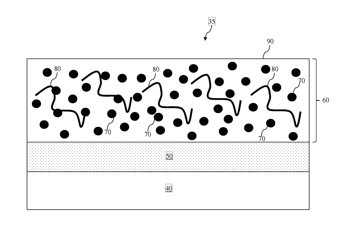
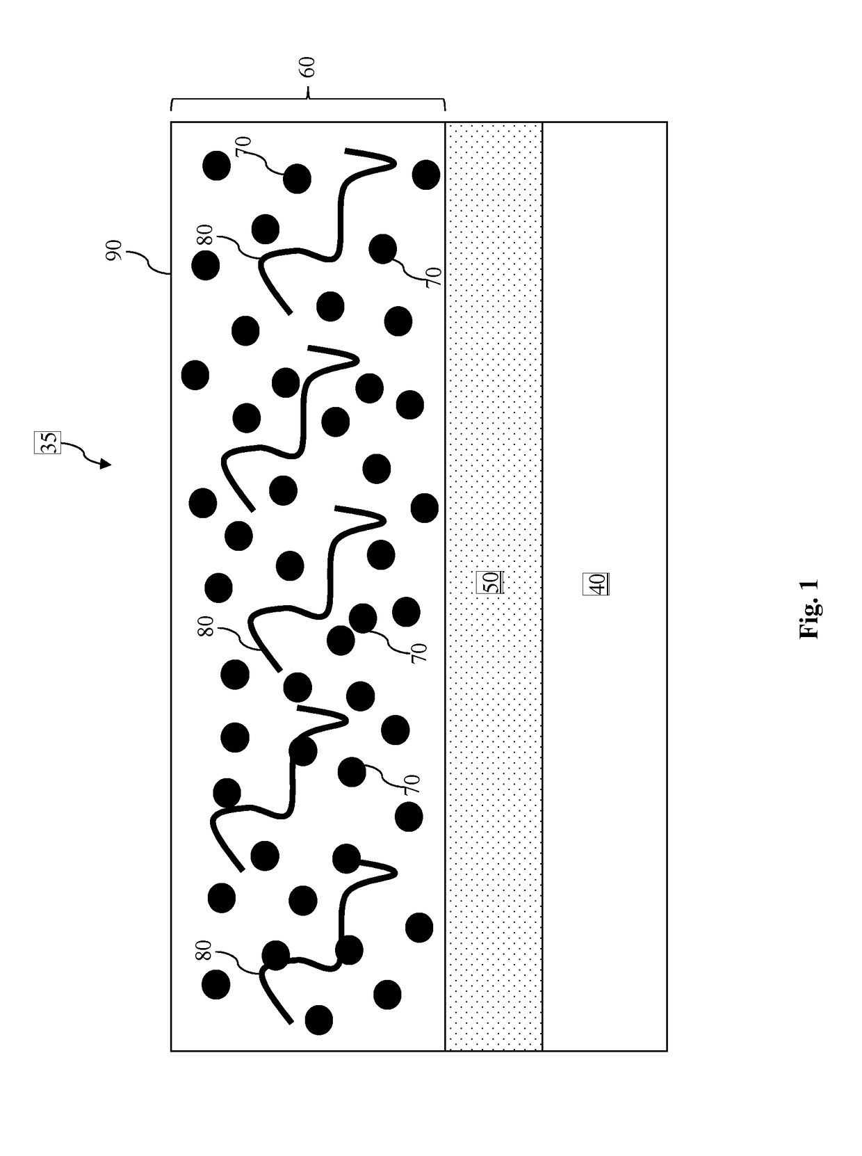
[0009]The following disclosure provides many different embodiments, or examples, for implementing different features of the provided subject matter. Specific examples of components and arrangements are described below to simplify the present disclosure. These are, of course, merely examples and are not intended to be limiting. For example, the formation of a first feature over or on a second feature in the description that follows may include embodiments in which the first and second features are formed in direct contact, and may also include embodiments in which additional features may be formed between the first and second features, such that the first and second features may not be in direct contact. In addition, the present disclosure may repeat reference numerals and / or letters in the various examples. This repetition is for the purpose of simplicity and clarity and does not in itself dictate a relationship between the various embodiments and / or configurations discussed.

[0010]F...


PUM

PropertyMeasurementUnit
wavelengthaaaaaaaaaa
sizesaaaaaaaaaa
dielectric constantaaaaaaaaaa

Abstract

A patternable layer is formed over a substrate. A photo-sensitive layer is formed over the patternable layer. The photo-sensitive layer contains an additive. The additive contains at least a floating control chemical and a volume control chemical. A spin drying or a baking process is performed to the photo-sensitive layer. The floating control chemical causes the additive to rise upward during the spin drying or baking process. Thereafter, as a part of an extreme ultraviolet (EUV) lithography process, the photo-sensitive layer is exposed. One or more outgassing chemicals are generated inside the photo-sensitive layer during the exposing. The volume control chemical is sufficiently voluminous and dense to trap the outgassing chemicals inside the photo-sensitive layer.

Description

PRIORITY DATA[0001]This application claims priority to Provisional Patent Application No. 62 / 115,671, filed Feb. 13, 2015, and entitled “Novel Photoresist Additive for Outgassing Reduction and Out-of-Band Radiation Absorption,” the disclosure of which is hereby incorporated by reference in its entirety.BACKGROUND[0002]The semiconductor integrated circuit (IC) industry has experienced rapid growth. Technological advances in IC materials and design have produced generations of ICs where each generation has smaller and more complex circuits than the previous generation. However, these advances have increased the complexity of processing and manufacturing ICs and, for these advances to be realized, similar developments in IC processing and manufacturing are needed. In the course of integrated circuit evolution, functional density (i.e., the number of interconnected devices per chip area) has generally increased while geometry size (i.e., the smallest component (or line) that can be crea...

Claims


Application Information

Patent Timeline
Patent Type & Authority Patents(United States)
IPC IPC(8): G03F7/004H01L21/033C08F220/22C08F18/04B05D3/00H01L21/027G03F7/16G03F7/20G03F7/039G03F7/09G03F7/11
CPCG03F7/091H01L21/033C08F18/04C08F220/22G03F7/0046G03F7/0392G03F7/0395G03F7/0397G03F7/11G03F7/16G03F7/2041H01L21/0271H01L21/0274H01L21/0276B05D3/007
Inventor LAI, WEI-HANCHANG, CHING-YUWANG, CHIEN-WEI
Owner TAIWAN SEMICON MFG CO LTD
Why Eureka
Try Eureka