Two-way antenna mounting bracket and assembly with independently adjustable electromechanical antenna tilt and azimuthal steering for beam reshaping

a technology of electromechanical antenna tilt and azimuthal steering and antenna mounting bracket, which is applied in the direction of antennas, antenna details, electrical equipment, etc., can solve the problems of skewed antenna radiation footprint coverage, dangerous adjustments, labor intensive and cost-intensive, etc., and achieve accurate network coverage, fast and reliable mobile broadband connections, and increase system capacity

Inactive Publication Date: 2018-05-15
OUTTHINK TECH LLC
View PDF12 Cites 3 Cited by
  • Summary
  • Abstract
  • Description
  • Claims
  • Application Information

AI Technical Summary

Benefits of technology

[0016]Accordingly, it is one object of the present invention to provide an antenna assembly that enables delivery of fast and reliable mobile broadband connections, correct signal propagation, and accurate network coverage throughout an entire lifecycle of a mobile communications base station. It is another object of the present invention to provide an antenna assembly that enables antenna alignment and pattern changes to increase system capacity and allow for smooth network operation in time-varying traffic conditions. It is a further object of the present invention to provide a system and method of antenna mounting in which both antenna direction and inclination are remotely adjustable.
[0017]It is another object of the present invention to provide a high-load electromechanical remote mechanical tilt arrangement, ensuring both up and down tilt antenna adjustment with absolute reference to the local horizontal plane without requiring working above ground, while allowing both remote mechanical tilt adjustment and manual mechanical tilt operation. It is still another object of the present invention to provide an electromechanical remote azimuth steering arrangement with an integrated motor and gearing assembly, allowing both remote azimuth steering and manual operation without losing the calibration between the motor and the antenna azimuth setting once user intervention is required.
[0018]Another object of the present invention is to provide an electromechanical remote azimuth steering arrangement with an integrated antenna orientation sensor to accurately align the antenna bracket to the boresight setting, measuring all orientation parameters including antenna azimuth with respect to True or Grid North, tilt and roll with respect to the horizontal plane, as well as antenna latitude, longitude and altitude. An additional object of the present invention is to provide an electromechanical remote azimuth steering arrangement with an integrated highly efficient backlash-free gear system providing antenna rotation slow-down and position sustain.
[0021]In one embodiment of the present invention, an assembly for a mobile communications system comprises an antenna array including one or more radiating elements; a stationary backbone pole; an antenna azimuth steering arrangement comprising a rotating pole, a plurality of bracket arms coupling the antenna array to the rotating pole, a steering drive unit linked to the rotating pole by a coupler at a lower end of the rotating pole, the steering drive unit configured to control movement of the rotating pole about the rotational portion of each linkage arm and, so as to electromechanically adjust an azimuthal angle of the antenna array relative to a reference axis and to prevent unintended movement of the rotating pole; a mounting brace coupling the antenna azimuth steering arrangement to the stationary backbone pole; an antenna tilting arrangement comprising a first telescopic mechanical tilt system attached to an upper end of the antenna array and to the rotating pole proximate to the rotational portion of a linkage arm at an upper end of the rotating pole by a first mounting clamp, a second telescopic mechanical tilt system attached to a lower end of the antenna array and to the rotating pole proximate to the rotational portion of a linkage arm at a lower end of the rotating pole by a second mounting clamp, the first and second telescopic mechanical tilt systems configured to adjust a tilt angle of the antenna array relative to the upper end of the rotating pole and to the lower end of the rotating pole, so as to electromechanically adjust the tilt angle of the antenna array relative to a reference plane and to prevent unintended movement of the antenna array; and an antenna orientation sensor that enables accurate alignment of the antenna array by measuring orientation parameters, and tilt and roll with respect to a horizontal plane.
[0022]In another embodiment, the present invention includes an apparatus comprising a mobile network communications array including a plurality of antenna elements for directing a beam of electromagnetic energy in a desired propagation direction and at a desired inclination; and a bracket assembly for supporting and positioning the plurality of antenna elements to independently and variably achieve the desired propagation direction and the desired inclination, the bracket assembly including at least one of an antenna tilt system configured to electromechanically or manually adjust both an upper end bracket arm and a lower end bracket arm of the mobile network communications array relative to a reference plane to shape an antenna radiation pattern, and an azimuth angle steering system configured to electromechanically or manually adjust an azimuth angle of the mobile network communications array by rotating the rotating pole relative to a reference axis to shape the antenna radiation pattern, the azimuth angle steering system including a steering drive unit having an integrated motor and gearing assembly that allows both remote azimuth steering and manual operation without a calibration loss between a motor and an antenna azimuth setting once user intervention is required.
[0023]In still another embodiment, the present invention includes a method of adjusting an inclination and direction of an antenna array in a mobile communications network, comprising adjusting a tilt angle of an antenna array at both an upper end bracket arm and a lower end bracket arm of an assembly coupling the antenna array to a support structure, and relative to a reference plane, to shape an antenna radiation pattern and direct a beam of electromagnetic energy at a desired inclination by horizontal, vertical and pivotal displacement of the assembly; adjusting an azimuth angle of the antenna array by rotating a rotating pole relative to a reference axis, to shape the antenna radiation pattern and direct a beam of electromagnetic energy in a desired propagation direction; and steering a tilting movement of the antenna array relative to the reference plane by a tilting drive unit, and a rotational movement of the rotating pole by an azimuth steering drive unit, to independently and variably achieve the desired propagation direction and the desired inclination.

Problems solved by technology

Consequently, human intervention is required, making the adjustments dangerous, labor intensive and cost-inefficient.
Furthermore, these methods demonstrate skewed antenna radiation footprint coverage when the antenna is offset with respect to the antenna boresight setting due to the fact that the mechanical tilt axis lies behind the azimuth steering axis.
Additionally, prior art antenna mounting brackets featuring remote down-tilt methods cannot sustain high force loads due to mechanical design limitations.
Moreover, they typically employ an electromechanical actuator comprising a coupled motor and a gear set without incorporating provisions for manually adjusting the mechanical tilt of the antenna beam in case of field service or component failure.
Current methods of antenna remote azimuth steering (RAS) in the prior art also do not incorporate provisions for manually adjusting the azimuth of the antenna beam in case of field service or component failure.
Also, due to the importance of accurate antenna pointing to a reference azimuth and mechanical tilt direction, in order to minimize signal quality degradation, the use of complex alignment tools and geographic landmarks or electronic alignment devices to install the antenna bracket to the boresight setting is not recommended as they fail to provide the optimal antenna alignment due to a multitude of reasons such as multipath errors, soft and hard iron disturbances, lack of alignment with the antenna back etc. . Systems providing remote azimuth steering (RAS) functionalities that retain the antenna in the desired azimuth direction solely using a high-ratio gearbox, without incorporating any provisional means of reducing stress induced to the gearbox components by rapid load changed due to external forces, may experience mechanical looseness, eccentric shafts, gear wear, broken teeth, and bearing wear.
However, digital compasses relying on the earth's magnetic field to provide heading are subject to hard and soft iron errors, acceleration errors, and severe inclinations that increase heading calculation complexity and measurement inaccuracy.
As a result, an electrical failure may risk the system's operability.
Thus, it does not provide a remotely-controlled antenna mechanical tilt adjustment mechanism.
However, as explained in the previous paragraph, such antenna heading adjustment techniques are not optimal.
However, the system does not provide mechanical up-tilt which is often employed in mobile network design and optimization in tandem with electrical tilt to reduce signal interference between neighboring sites by greatly suppressing antenna radiation pattern side lobes.
Thus, an electrical failure may risk the system's operability.
However, this breaking arrangement may not meet the increased load requirements of advanced ultra-wideband and multi-band mobile base station antenna arrays.
Thus, accurate azimuth alignment with respect to True or Grid North cannot be accomplished.
Furthermore, no provisions for detecting and compensating for non-vertical orientation of the antenna mount are provided.
Also, despite the fact that the antenna mount includes arrangements preventing the antenna from exceeding the maximum allowable vertical travel, no such arrangements exist for the horizontal plane.
Thus, as with other systems, an electrical failure may risk the system's operability.
However, as clarified above, the antenna's tilted azimuth rotation axis, that is parallel to the reference frame tilted axis, results in an inclined orbit with respect to the horizontal plane and in an adverse skewed antenna radiation pattern.
Thus, both modes of operation cannot be combined in a single unit resulting in system operability risk in case of an electrical failure.
Thus, it does not provide a remotely-controlled antenna mechanical tilt adjustment mechanism.

Method used


Image

  • Two-way antenna mounting bracket and assembly with independently adjustable electromechanical antenna tilt and azimuthal steering for beam reshaping
  • Two-way antenna mounting bracket and assembly with independently adjustable electromechanical antenna tilt and azimuthal steering for beam reshaping
  • Two-way antenna mounting bracket and assembly with independently adjustable electromechanical antenna tilt and azimuthal steering for beam reshaping

Examples


Embodiment Construction

[0056]In the following description of the present invention reference is made to the exemplary embodiments illustrating the principles of the present invention and how it is practiced. Other embodiments will be utilized to practice the present invention and structural and functional changes will be made thereto without departing from the scope of the present invention. The accompanying drawings, which are incorporated in and constitute a part of this specification, illustrate several embodiments of the invention and together with the description, serve to explain the principles of the invention.

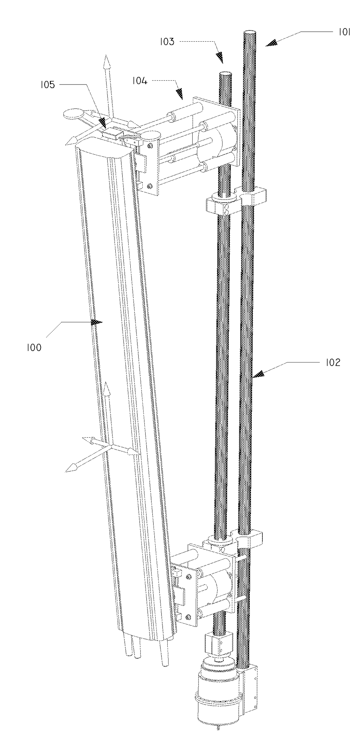
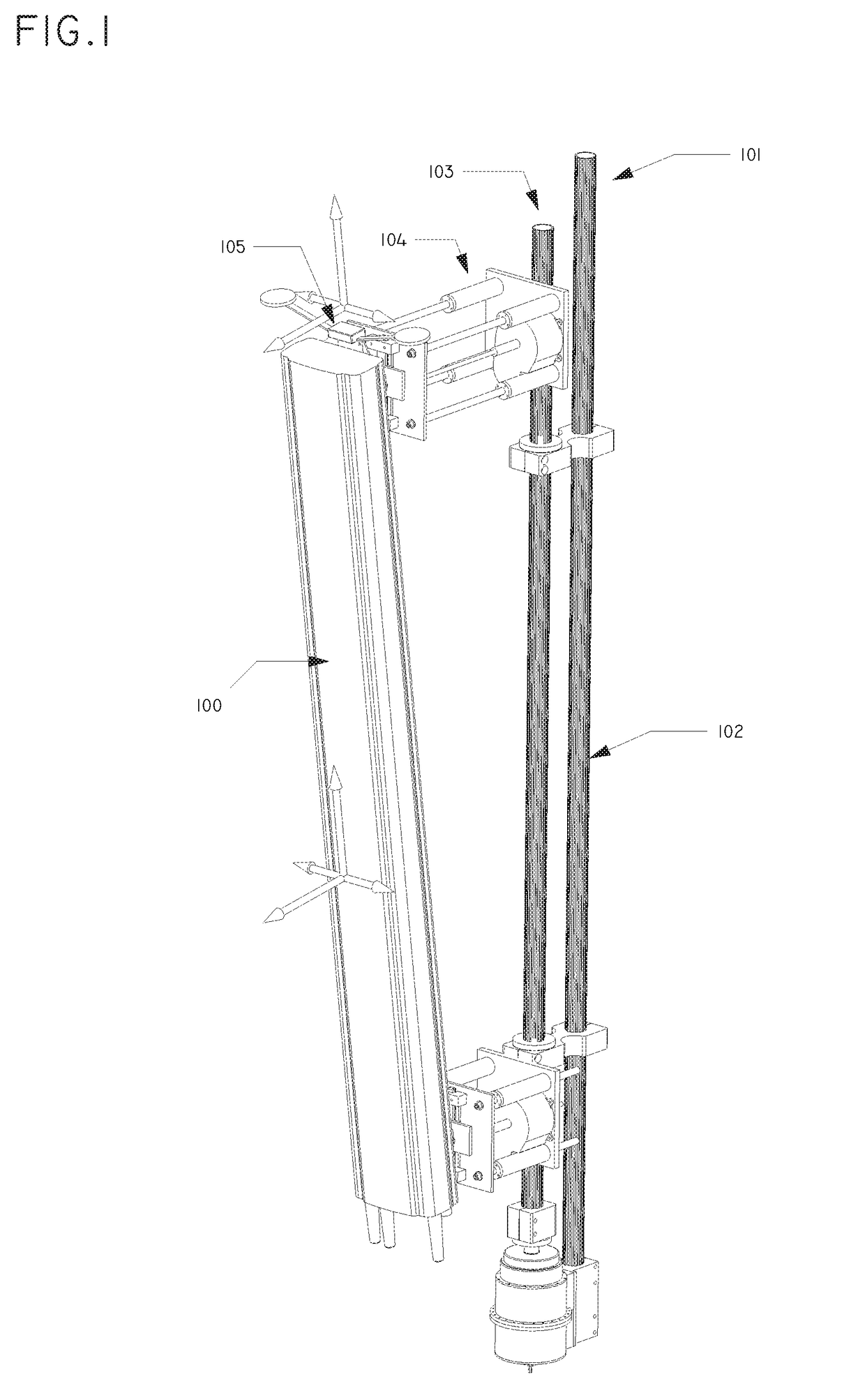
[0057]FIG. 1 illustrates a perspective view of an antenna array 100 mounted on a two-way antenna mounting bracket assembly 101 according to an exemplary implementation of the present invention. The two-way antenna mounting bracket assembly 101 comprises a stationary backbone pole 102 that is attached to a mounting support structure using bottom and top mounting brackets, an electromechanical ...


PUM


Abstract

An assembly for a mobile communications antenna system includes a bracket assembly onto which an antenna array is mounted. The bracket assembly includes a steering arrangement configured to provide angular adjustment of an antenna beam azimuth, and an electromechanical tilting arrangement configured to adjust a tilt position of the antenna array. The steering arrangement and the electromechanical tilting arrangement are controllable in remote and manual operational modes to independently and variably adjust both azimuthal angle and tilt position of the antenna array. These operational modes ensure remote control of signal propagation and network coverage accuracy, and manual adjustment of the azimuth of the antenna beam and tilt position of the antenna array in case of field service or component failure.

Description

CROSS-REFERENCE TO RELATED PATENT APPLICATION(S)[0001]This patent application claims priority to U.S. provisional application No. 62 / 103,599, filed on Jan. 15, 2015, the contents of which are incorporated in their entirety herein. In accordance with 37 C.F.R. § 1.76, a claim of priority is included in an Application Data Sheet filed concurrently herewith.FIELD OF THE INVENTION[0002]The present invention relates to systems and components of a mobile communications base station infrastructure. More particularly, the present invention is an apparatus, method, and system for providing remote azimuth steering and remote electromechanical tilting functions for any mobile communications base station antenna.BACKGROUND OF THE INVENTION[0003]In modern mobile communications networks, most importantly in 4th Generation (4G) Long Term Evolution (LTE) networks, antenna alignment is vital for delivery of fast and reliable mobile broadband connections, correct signal propagation, and spot-on netwo...

Claims


Application Information

Patent Timeline
Patent Type & Authority Patents(United States)
IPC IPC(8): H01Q1/12H01Q3/08H01Q1/24
CPCH01Q3/08H01Q1/125H01Q1/1228H01Q1/246H01Q1/1207
Inventor VASSILAKIS, BILL
Owner OUTTHINK TECH LLC
Why Eureka
Try Eureka