Optical information recording/reproducing apparatus, optical information recording/reproducing method

a technology of optical information and recording equipment, applied in the direction of optical recording/reproducing/erasing methods, optical beam sources, instruments, etc., can solve the problem of stringent tolerability of hdss to physical perturbation such as mechanical instability

Active Publication Date: 2018-05-22
THE ARIZONA BOARD OF REGENTS ON BEHALF OF THE UNIV OF ARIZONA +1
View PDF2 Cites 0 Cited by
  • Summary
  • Abstract
  • Description
  • Claims
  • Application Information

AI Technical Summary

Problems solved by technology

However, tolerances of HDSS to physical perturbation such as mechanical instability needs to be stringent in return for the associated high density recording.

Method used


Image

  • Optical information recording/reproducing apparatus, optical information recording/reproducing method
  • Optical information recording/reproducing apparatus, optical information recording/reproducing method
  • Optical information recording/reproducing apparatus, optical information recording/reproducing method

Examples


first embodiment

(First Embodiment)

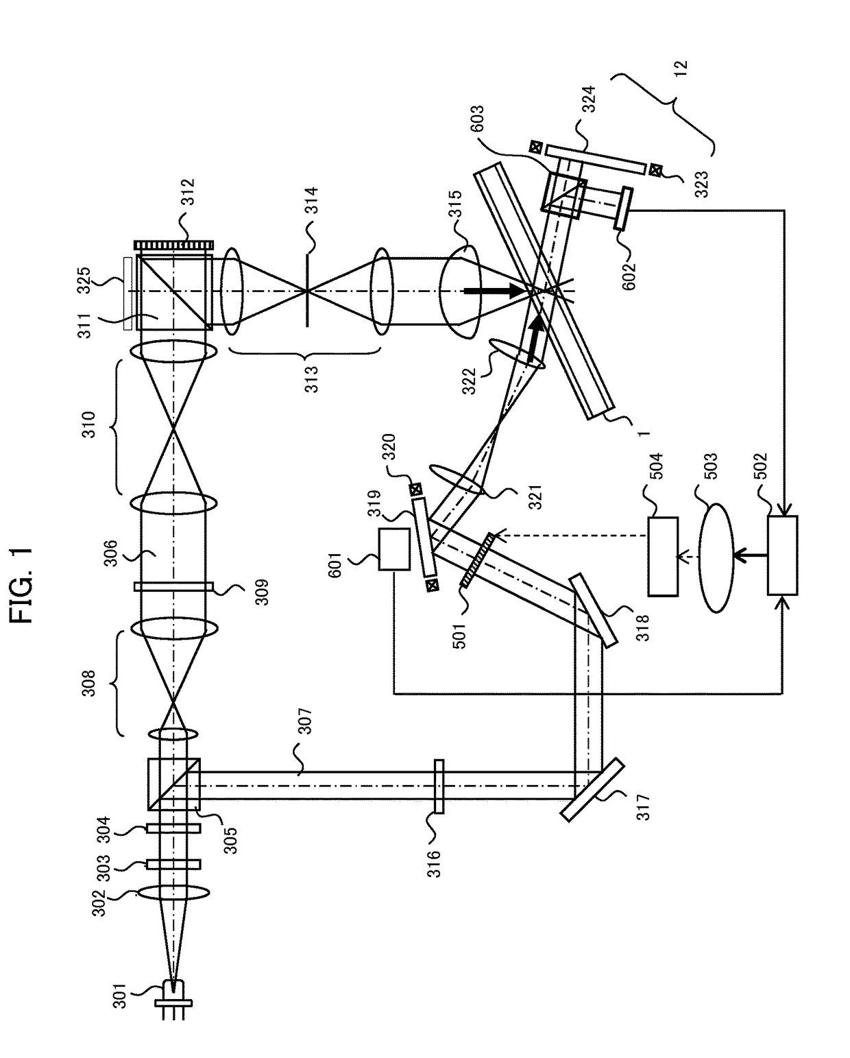
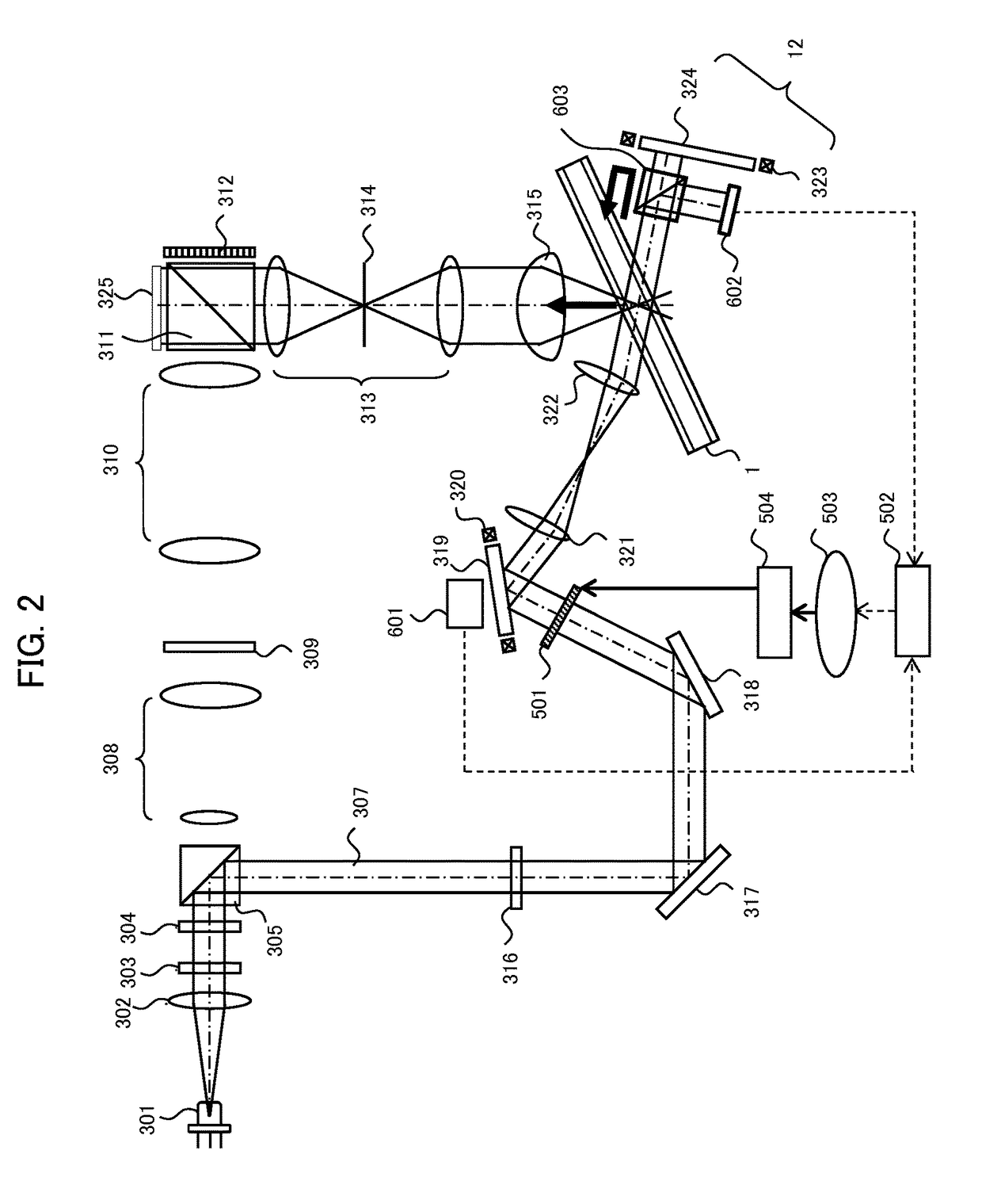
[0032]A first embodiment of the invention will be described with reference to FIG. 1. FIG. 1 shows a recording principle of an example of a basic optical system in the optical information recording / reproducing apparatus. A light beam emitted from a variable wavelength laser 301 of an external resonator type (as an example of a light source) is collimated by a collimating lens 302 and directed to a shutter 303. When the shutter 303 is opened, the light beam is passed through the shutter 303 and through an optical element 304 formed, for example, as a ½ wavelength plate. The optical element 304 provides polarization direction control so that a beam ratio of P and S polarization becomes a desired value, and then the beam is directed into the PBS (Polarization Beam Splitter) prism 305.

[0033]One light beam passed through the PBS prism 305 works as a signal beam 306. The light beam is enlarged in diameter by a beam expander 308, is passed through a phase mask 309, a rela...

second embodiment

(Second Embodiment)

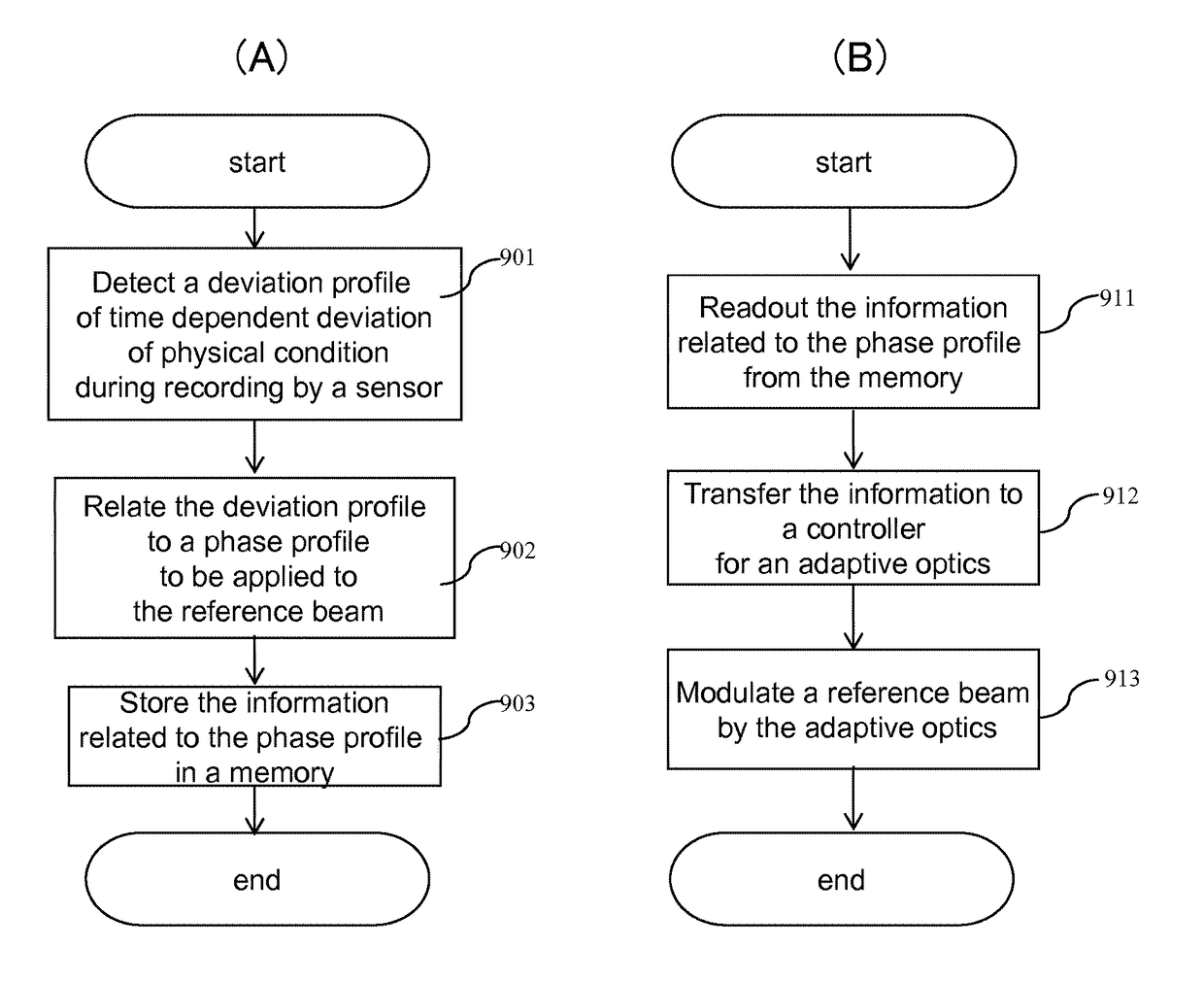
[0080]A second embodiment of the invention will be described with reference to FIG. 8. In this embodiment, the control signal for the adaptive optics 501 is produced according to a design specification of a servomechanism for components in the system. In other words, the control signal is predetermined according to a design specification of a servomechanism for such as the galvano mirror. Therefore, a sensor in order to detect physical condition of components or optical beam is not necessarily required. In this embodiment, the deviation profiler can be a control signal derived from a design specification of a servomechanism, utilized to control the adaptive optics 501 during reproduction of the hologram. The control signal may be applied to the adaptive optics 501 during recording as described in FIG. 9 instead of during reproducing because almost the same compensation effect can be achieved as described in Eq. (6) and Eq. (7). The adaptive optics 501 may have a p...


PUM

PropertyMeasurementUnit
incident angleaaaaaaaaaa
phaseaaaaaaaaaa
angleaaaaaaaaaa

Abstract

An optical information recording / reproducing apparatus and method thereof which compensate for the effect of mechanical instability on holographic data storage. A time dependent deviation profile of an optical beam during recording is determined. The time dependent deviation profile is related to a phase profile to be applied to a reference beam during recording or reproduction of a hologram, and the related phase profile is applied to the reference beam during recording or reproduction of the hologram.

Description

BACKGROUND OF THE INVENTION[0001]Field of the Invention[0002]The present invention is related to an apparatus and method which record and / or reproduce information on an optical information recording medium by using holography.[0003]Description of the Related Art[0004]Through a BLU-RAY DISC™ specification using a blue-violet semiconductor laser, at present, commercialization of optical disk having recording density of about 100 GB is presently performed. From now on, large capacity greater than 500 GB is expected from optical disk recording. However, for realizing the above-described ultra-high density by using an optical disk, a high-density technology is needed through another method which is different from a high-density technology using the conventional short wavelength and high numerical aperture of objective lens.[0005]Holographic Data Storage System (HDSS) has been considered as one of promising candidates for future Optical Data Storage (ODS) systems. HDSS can record an encod...

Claims


Application Information

Patent Timeline
Patent Type & Authority Patents(United States)
IPC IPC(8): G11B7/0065G11B7/1362G03H1/14G02B26/08G03H1/22G03H1/04G11B7/126
CPCG03H1/14G02B26/0816G03H1/0486G03H1/2286G11B7/0065G11B7/1362G11B7/126G03H2226/02G03H2001/0489G03H2222/42G03H2223/24G11B7/08564G11B7/1369
Inventor TAKASHIMA, YUZURUSHIMADA, KENICHI
Owner THE ARIZONA BOARD OF REGENTS ON BEHALF OF THE UNIV OF ARIZONA
Why Eureka
Try Eureka