Rounded and curved integrated tethers for quartz resonators

a quartz resonator and integrated technology, applied in the field of tethers, can solve the problems of low yield, difficult simulation prediction of observation, extraneous modes, etc., and achieve the effects of reducing phase noise vibration sensitivity, reducing the footprint, and minimizing or eliminating extraneous modes

Active Publication Date: 2018-06-05
HRL LAB
View PDF259 Cites 9 Cited by
  • Summary
  • Abstract
  • Description
  • Claims
  • Application Information

AI Technical Summary

Benefits of technology

[0014]Using a resonator design in accordance with principles of the present invention, quartz and Si gyro resonators can be integrated with a very small footprint that is no larger than a gyroscope itself. This produces a small and rigid package for e.g. air and ground vehicle navigation systems. By using doubly clamped rounded and curved tethers, the phase noise vibration sensitivity can also be reduced in high-g environments.
[0015]In one embodiment, the proposed quartz resonator

Problems solved by technology

This is an experimental observation that is difficult to predict through simulations.
Unless the integrated tethers have ro

Method used


Image

  • Rounded and curved integrated tethers for quartz resonators
  • Rounded and curved integrated tethers for quartz resonators
  • Rounded and curved integrated tethers for quartz resonators

Examples


Embodiment Construction

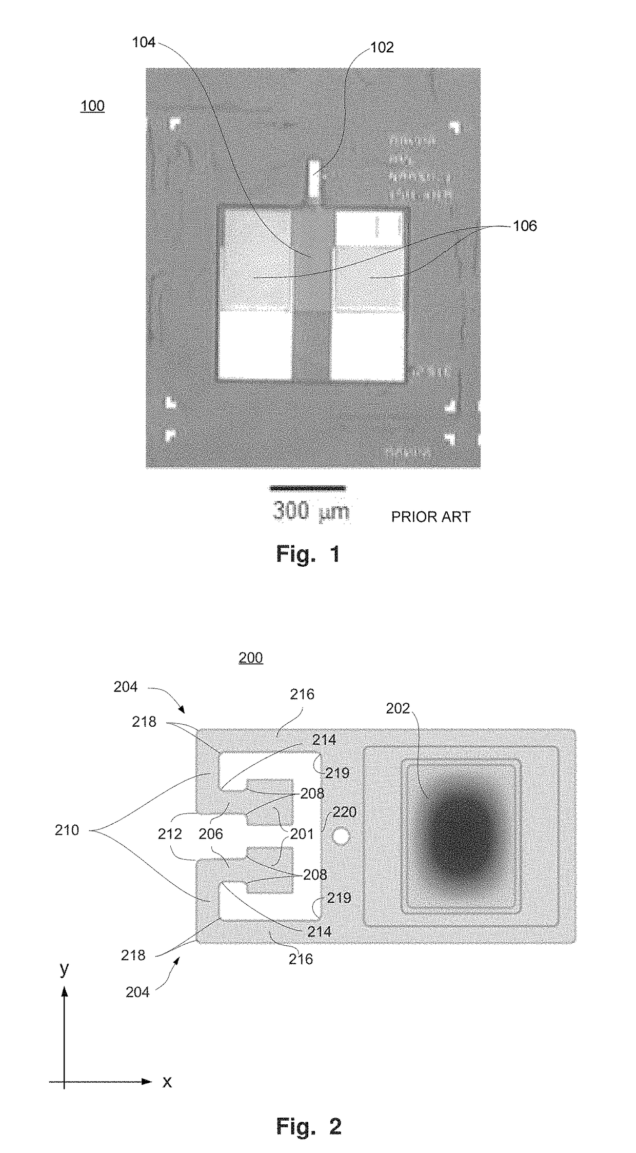
[0027]Quartz MEMS resonators can be integrated to semiconductor substrates using wafer-level processes in a known manner. FIG. 1 is a plan diagram of a MEMs-based quartz resonator without tethers between bond pads and the resonator. In FIG. 1, a substrate 100 has a quartz plate 104 bonded to it and a quartz resonator 102 is fabricated from the quartz plate 104. Bond pads 106 are used to bond the resonator 102 to corresponding pads on the substrate.

[0028]The bond of the quartz plate 104 to the semiconductor substrate 100 is typically produced using a Au / In eutectic bond which can be initially created at low bond temperatures (<150° C.). The metallization can then be interdiffused at a higher temperature to form a robust attachment that can withstand much higher temperature processing for vacuum packaging and die attachment processes. The Au / In is deposited at wafer level. The typical geometry of this bonding area relative to the active region of the resonator is shown in FIG. 1.

[0029...


PUM


Abstract

A piezoelectric quartz shear-mode resonator includes plasma etched quartz tethers, each including a mount. The tethers are for mounting the resonator to a semiconductor substrate for the purpose of isolating the thermally-induced stress from the mounts from the active resonating region, wherein the quartz tethers have rounded corners.

Description

CROSS-REFERENCE TO RELATED APPLICATIONS[0001]The present application claims priority from provisional application 61 / 976,944, filed Apr. 8, 2014, and titled “Tethers for Quartz Resonators” the disclosure of which is incorporated by reference herein.STATEMENT REGARDING FEDERALLY SPONSORED RESEARCH OR DEVELOPMENT[0002]This invention was made with Government support under Contract No. withheld / N66001--13--C--4020 Co--Integration of High--Aspect--Ratio Si Gyros & Quartz Clocks for Improved Inertial Performance. The Government has certain rights in the invention.BACKGROUND OF THE INVENTIONField of the Invention[0003]The present invention relates to mounting microelectro-mechanical system (MEMS) components on a substrate, and in particular to tethers for reducing stress on the MEMS component and increasing fabrication yield.Discussion of the Related Art[0004]Because characteristics of nearly all electronic components vary with temperature, to maintain accuracy it is desirable for them to ...

Claims


Application Information

Patent Timeline
IPC IPC(8): H03H9/19H03H3/007H03H3/02
CPCH03H3/0076H03H9/19H03H2003/027H03H9/02062H03H9/0514
Inventor KUBENA, RANDALL L.KIRBY, DEBORAH J.CHANG, DAVID T.
Owner HRL LAB
Why Eureka
Try Eureka