LED lighting device having a structural design that effectively increases the surface area of the circuit board for circuit layout

a technology of circuit layout and lighting device, which is applied in the direction of lighting support device, fixed installation, lighting and heating apparatus, etc., can solve the problems of high power consumption, fast light attenuation, and conventional lamp bulb or lamp tube type lighting device, so as to improve the overall configuration and use flexibility, increase the diameter, and increase the available surface area

Inactive Publication Date: 2018-06-12
CHICONY POWER TECH CO LTD
View PDF9 Cites 3 Cited by
  • Summary
  • Abstract
  • Description
  • Claims
  • Application Information

AI Technical Summary

Benefits of technology

[0007]The present invention has been accomplished under the circumstances in view. It is therefore the main object of the present invention to provide a LED lighting device, which comprises a LED light housing and a LED light-emitting module. The LED light housing comprises a hollow outer shell, a reflector cup mounted in the hollow outer shell, and a lens mounted in the reflector cup. The hollow outer shell comprises an accommodation chamber, an opening located in a bottom side thereof to connect with the accommodation chamber and the space outside the LED light housing, and a planar mounting surface located in the accommodation chamber. The reflector cup comprises a lens mounting hole located on the center thereof and a conical reflective surface defined therein and gradually increased in diameter from the lens mounting hole toward an opposing bottom open side of the reflector cup. The lens comprises a light exit surface facing toward the conical reflective surface of the reflector cup. The LED light-emitting module comprises a circuit board mounted between the planar mounting surface of the hollow outer shell and the lens and defining a front side and an opposing back side, a plurality of light-emitting diodes arranged on a center area of the front side of the circuit board to face toward the light exit surface of the lens, a control circuit comprising a driver IC mounted in a border area at the front side of the circuit board and a capacitor mounted on the back side of the circuit board, and a power cord electrically coupled with the circuit board and the driver IC and extended out of the back side of the circuit board for connection to an external power source. This structural design effectively increases the available surface area of the circuit board for circuit layout and the related circuit layout insulation distance, enabling the light-emitting diodes, the driver IC, the capacitor and other related components to be properly arranged on the circuit board and enhancing the flexibility of the overall configuration and use of space. This structural design also allows installation of a relatively larger amount of light-emitting diodes in the center area of the front side of the circuit board, increasing the overall brightness of the light-emitting diodes. Further, the use of the driver IC with the capacitor effectively solves the problems of flashing and dimming matching with a conventional TRIAC.
[0008]Further, the detachable mounting design of the hollow outer shell and reflector cup of the LED light housing simplifies the fabrication of the hollow outer shell with one single mold, and different model designs or different sizes of reflector cups can be selectively used and assembled with the lens to match with the hollow outer shell. Thus, the invention allows mass production of the component parts of the LED lighting device. Installation of the circuit board of the LED light-emitting module between the hollow outer shell and the lens is simple, convenient and detachable. This detachable mounting design facilitates replacement and maintenance of the component parts. Further, the conical reflective surface of the reflector cup can be coated with a reflective layer of white, silver or aluminum coating, enhancing the light reflecting performance of the conical reflective surface in reflecting light to the lens toward the outside of the LED lighting device. Further, the light exit surface of the lens can be configured to provide different grain patterns to achieve different effects on light transmission.
[0009]Further, the light-emitting diodes of the LED light-emitting module are made using CSP (Chip Scale Package) technology, and integrated with the driver IC of the control circuit into the front side of the circuit board using DOB (Driver on Board) technology and, the capacitor is arranged on the back side of the circuit board. This structural design effectively increases the available surface area of the circuit board for circuit layout and the related circuit layout insulation distance, enabling the light-emitting diodes, the driver IC, the capacitor and other related components to be properly arranged on the circuit board and enhancing the flexibility of the overall configuration and use of space. This structural design also allows installation of a relatively larger amount of light-emitting diodes in the center area of the front side of the circuit board, increasing the overall brightness of the light-emitting diodes and avoiding flashing.
[0010]Further, the power cord of the LED light-emitting module circuit is electrically coupled with the circuit layout on the back side of the board and extended out of the back side of the circuit board without interfering with the circuit layout on the front side of the circuit board. Further, the back side of the circuit board is closely attached to the planar mounting surface of the hollow outer shell to create a thermal path for enabling waste thermal energy to be transferred from the circuit board to the metal hollow outer shell for quick dissipation to the outside open air during the operation of the light-emitting diodes. Waste thermal energy can also be transmitted through the annular heat dissipation space and vent hole of the hollow outer shell for heat exchange with the outside cold air, enhancing the heat dissipation efficiency of the LED light-emitting module and achieving optimal cooling and heat dissipation.

Problems solved by technology

However, conventional lamp bulb or lamp tube type lighting devices have the drawbacks of quick light attenuation, high power consumption, large amount of waste heat and short lifespan.
However, conventional downlights have high brightness and can produce a high temperature during operation, causing thermal damage to commodities, counters, surrounding upholsteries.
Further, the lifespan of fluorescent lamps will be relatively reduced when working in a high temperature environment for a long time.
Making these mounting through holes on the LED circuit board B1 relatively reduces the available surface area of the LED circuit board B1 for circuit layout and the related circuit layout insulation distance, limiting the flexibility of the use of the overall space.
The use of this design of power driver greatly increases the cost of the electrical module C. Further, the operation of the power driver of the main control circuit board C1 to step down the voltage of the inputted AC power causes a certain amount of power conversion loss.

Method used


Image

  • LED lighting device having a structural design that effectively increases the surface area of the circuit board for circuit layout
  • LED lighting device having a structural design that effectively increases the surface area of the circuit board for circuit layout
  • LED lighting device having a structural design that effectively increases the surface area of the circuit board for circuit layout

Examples


Embodiment Construction

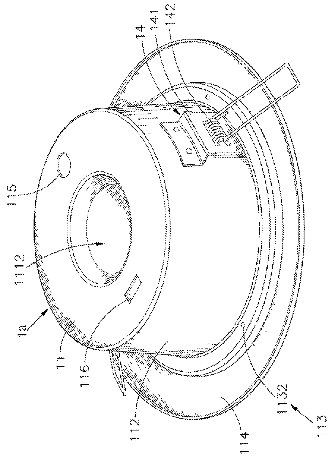
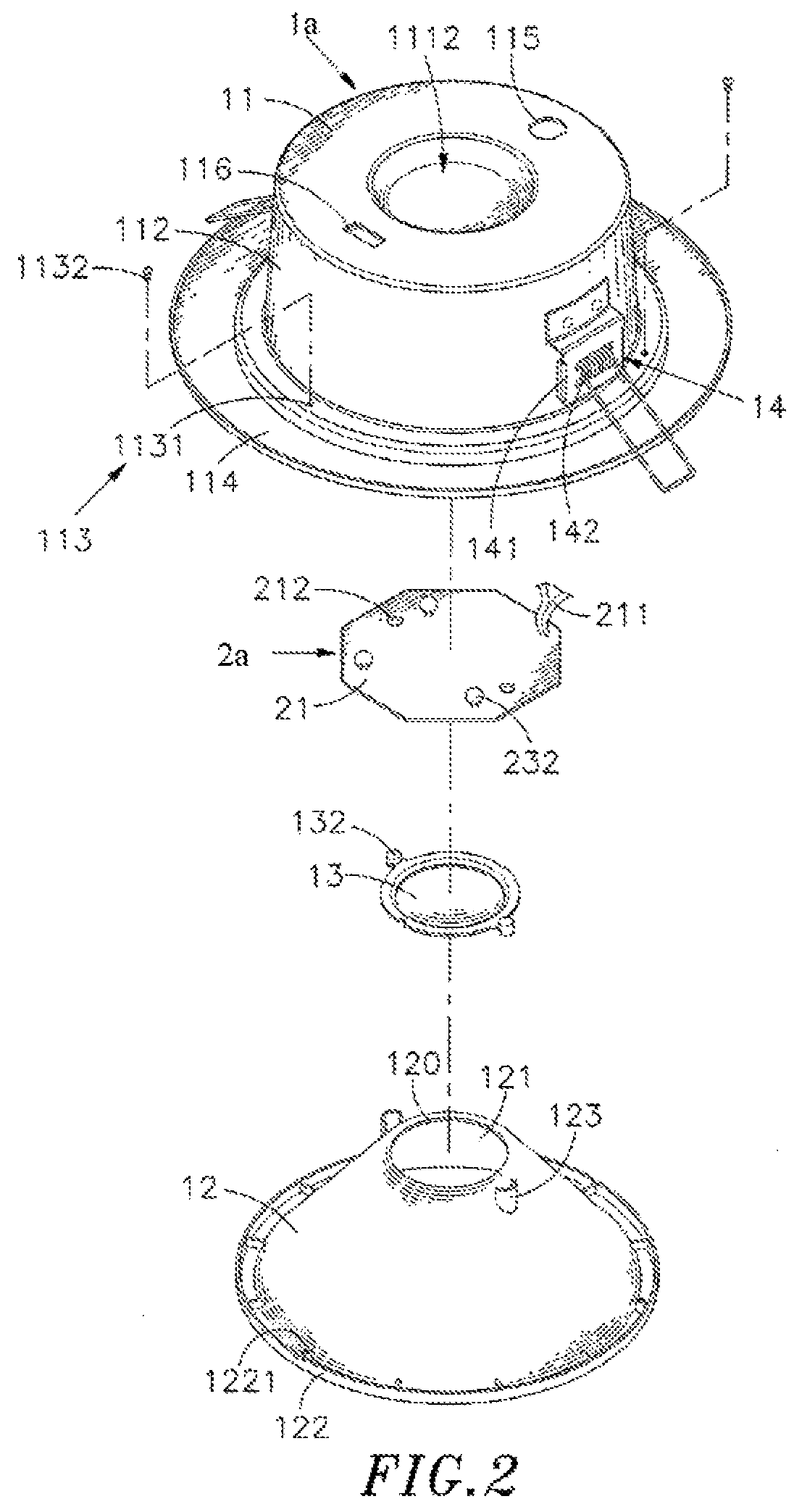
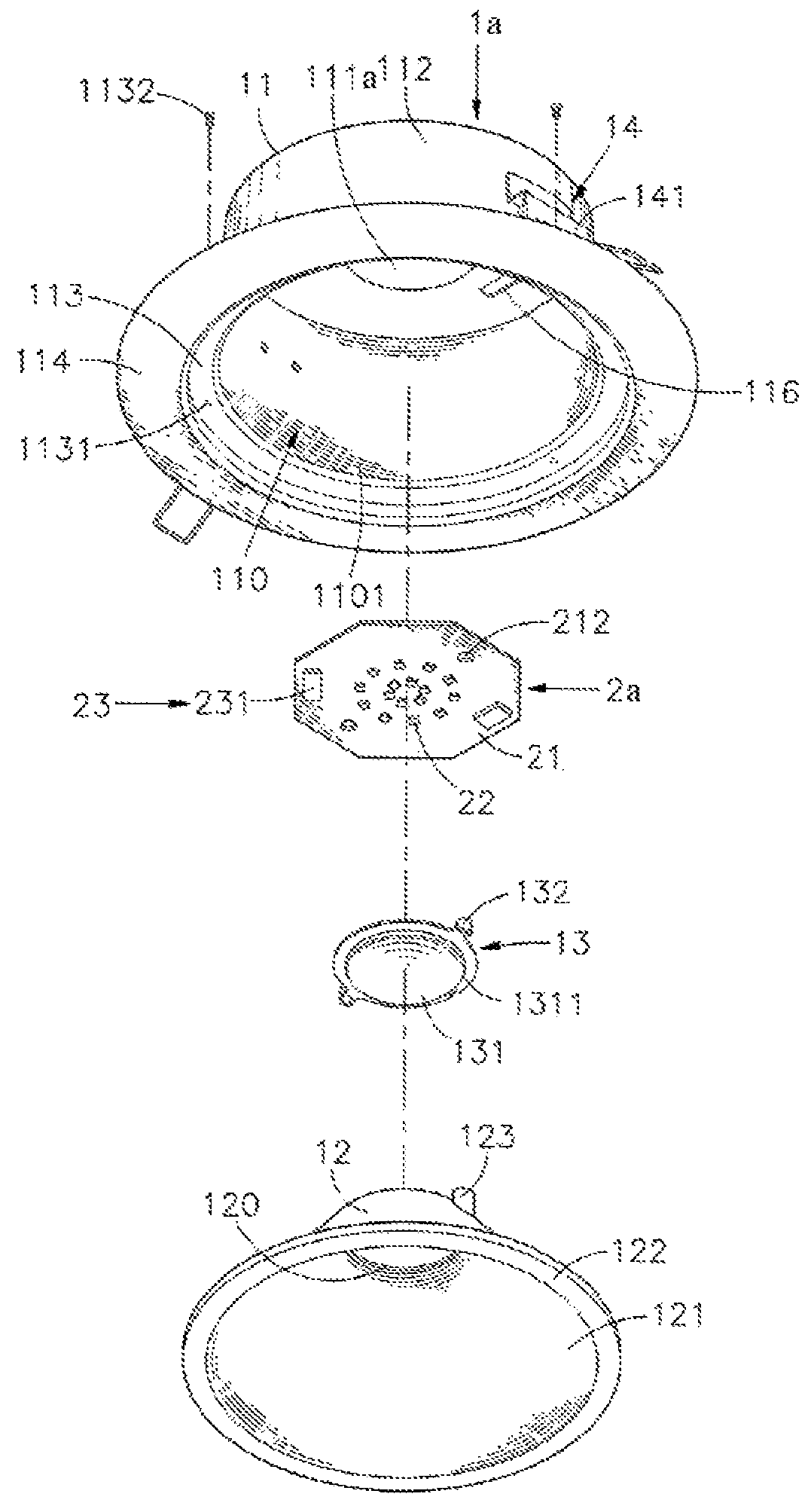
[0025]Referring to FIGS. 1-6, an oblique top elevational view of a LED lighting device in accordance with a first embodiment of the present invention, an exploded view of the LED lighting device, another exploded view of the LED lighting device, a front sectional exploded view of the LED lighting device and a front sectional assembly view of the LED lighting device are shown. As illustrated, in a first embodiment of the present invention, the LED lighting device comprises a LED light housing 1a and a LED light-emitting module 2a.

[0026]The LED light housing 1a comprises a hollow outer shell 11, a reflector cup 12, a lens 13, and a plurality of mounting devices 14. The hollow outer shell 11 comprises an accommodation chamber 110, an opening 1101 located in a bottom side thereof to connect with the accommodation chamber 110 and the outside space, a planar mounting surface 111a located on the center of a top side of the accommodation chamber 110 and facing toward the opening 1101, an a...


PUM


Abstract

LED lighting device includes LED light housing including hollow outer shell with planar mounting surface defined inner top side of accommodation chamber to face toward bottom opening and reflector cup mounted accommodation chamber and defining conical reflective surface therein and carrying lens at top center thereof with light exit surface of lens facing toward bottom opening of hollow outer shell, LED light-emitting module including circuit board mounted between planar mounting surface and lens, array of LEDs arranged front side of circuit board and control circuit with driver IC and capacitor thereof respectively arranged opposing front and back sides of circuit board for converting inputted AC power into stabilized DC power for driving LEDS. This structural design effectively increases available surface area of circuit board for circuit layout and related circuit layout insulation distance, allows installation of relatively larger amount of LEDs to increase overall brightness and makes reflector cup replaceable.

Description

CROSS REFERENCE TO RELATED APPLICATIONS[0001]This application is a continuation-in-part of and claims priority to Huan-Hsiang Huang, U.S. patent application Ser. No. 15 / 251,140, filed Aug. 30, 2016, entitled “LED LIGHTING DEVICE”, which is commonly assigned herewith, the entire contents of which are incorporated herein by reference with the same full force and effect as if set forth in its entirety herein, and with priority claimed for all commonly disclosed subject matter.BACKGROUND OF THE INVENTION1. Field of the Invention[0002]The present invention relates to LED lighting technology and more particularly, to a LED lighting device, which comprises a LED light housing consisting of a hollow outer shell, a reflector cup and a lens, and a LED light-emitting module having light-emitting diodes and a control circuit carried on a circuit board thereof, wherein the light-emitting diodes and a driver IC of the control circuit are arranged on a front side of the circuit board and a capacit...

Claims


Application Information

Patent Timeline
Patent Type & Authority Patents(United States)
IPC IPC(8): F21V15/01F21V23/00F21V17/12F21V29/508F21V21/30F21V19/00F21K9/20F21K9/69F21K9/68F21Y105/10F21Y115/10
CPCF21V23/005F21K9/20F21K9/68F21K9/69F21V15/01F21V19/003F21V23/002F21V29/508F21V17/12F21Y2115/10F21Y2105/10F21S8/02F21V7/041F21V19/0035F21V29/507F21V29/83F21Y2105/18
Inventor HUANG, HUAN-HSIANGSU, KUI-CHIH
Owner CHICONY POWER TECH CO LTD
Why Eureka
Try Eureka