Sensor apparatus

a sensor and apparatus technology, applied in the field of sensors, can solve the problems of inability apparatus is not able to provide temperature information, pressure sensitivity is an especially serious problem, etc., and achieve the effect of improving the performance of non-conta

Active Publication Date: 2018-06-12
FIORI JR DAVID
View PDF11 Cites 19 Cited by
  • Summary
  • Abstract
  • Description
  • Claims
  • Application Information

AI Technical Summary

Benefits of technology

[0014]The objective of this invention is to provide for the improved performance of non-contacting inductive magnetic field based position sensors in a resonant circuit when subject to extraneous capacitances that may introduce variations in the resulting oscillation frequency or period not related to the inductance variation which corresponds to the objective position function.

Problems solved by technology

None of these prior art disclosures teach any method to compensate for extraneous variations in the total capacitance that the sensor connections, sensor construction, or oscillator circuit effectively contribute to the total resonant capacitance.
To the extent that these extraneous contributions to the resonance capacitance change due to other unrelated effects, such as the temperature of portions of the apparatus whose temperature cannot be measured, and which affect the resulting position indication, they represent errors in position indication that the current art is unable to address in a cost effective manner if at all.
That apparatus is not able to provide temperature information without interrupting the development of sensor information because it requires that the oscillator is disabled and restarted every time the temperature is measured.
Such pressure sensitivity has been found to be an especially serious problem in applications where the sensor is immersed in hydraulic fluid under pressure.
Even in applications where the sensor is immersed in an unpressurized fluid, the dielectric properties of the fluid may also vary as the result of any number of factors that would also introduce errors in the position measurement related to changes in sensor capacitance that this inventor's previous disclosures could not address.

Method used


Image

  • Sensor apparatus
  • Sensor apparatus
  • Sensor apparatus

Examples


Embodiment Construction

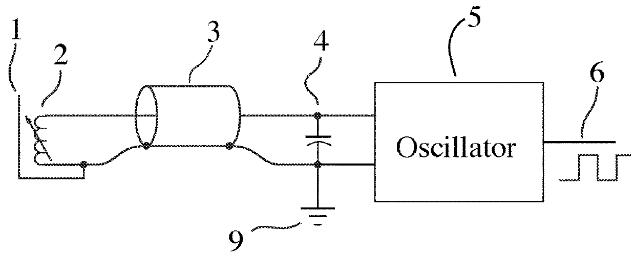
[0064]The preferred embodiment of this invention implements a system which measures the inductance of an inductive non-contacting position sensor in a parallel resonant circuit with essentially the same repeatability and insensitivity to environmental factors as a precision resistor. Simultaneously, the preferred embodiment of this invention also measures the temperature of the inductor in the most intimate and therefore most accurate way possible—by using the position sensor itself as a temperature sensor—in order to correct the precision measurement whose position function is naturally subject to significant temperature sensitivity which sensitivity is itself a strong function of the position. As the only variable the system is subject to after application of the capacitance compensating circuit disclosed herein is essentially the sensor inductance, and understanding that the only other variable significantly affecting the relationship between sensor inductance and position is tem...


PUM


Abstract

An improved sensor apparatus for developing a signal related to an inductive sensor in a resonant circuit are disclosed. This improvement is realized by adding a known capacitance to the resonant circuit and comparing the resulting natural resonance frequency to the frequency without the known capacitance. In this way a measure of the resonant capacitance is developed to correct the sensor signal for the effect of any changes in that capacitance. One disclosed embodiment adds an electronically variable capacitance which is adjusted to yield a constant capacitance that produces a sensor signal insensitive to variations in the resonant circuit capacitance. The resonant capacitance measurement may also provide an indication of another sensor state, such as temperature or pressure, which may be used to further correct for temperature or pressure sensitivities in the sensor signal. The invention is extended by juxtaposing the inductance for capacitance in the sensor resonant circuit.

Description

FIELD OF THE INVENTION[0001]The present invention relates, in general, to sensors which provide a signal related to their function by way of the variation in an electrical circuit reactance. This disclosure is particularly directed at the improvements to the electronic circuits which develop a signal responsive to the function of an inductive sensor when the sensor is combined with a capacitor to construct a resonant circuit. Non-contacting position sensors inductively coupled to moving parts are good examples of such inductive sensors. Pressure sensors with conductive diaphragms whose extension is a function of pressure which extension is measured by an inductive position or proximity sensor is another good example of an inductive sensor. The present disclosure is nevertheless directed to sensors whose function is related to variations in inductance, and whose accuracy is compromised by unwanted variations in various capacitance elements coupled to the sensor which result in errors...

Claims


Application Information

Patent Timeline
Patent Type & Authority Patents(United States)
IPC IPC(8): G01R27/26G01D5/24G01D5/20
CPCG01R27/2605G01R27/2611G01D5/20G01D5/24G01D3/036G01D5/243
Inventor FIORI, JR., DAVID
Owner FIORI JR DAVID
Why Eureka
Try Eureka