System for causing ablation of irradiated material of living tissue while not causing damage below a predetermined depth

Inactive Publication Date: 2000-09-12
LASER INDS
View PDF13 Cites 28 Cited by
  • Summary
  • Abstract
  • Description
  • Claims
  • Application Information

AI Technical Summary

Problems solved by technology

Such a temperature rise in underlying tissue may cause thermal damage or carbonization, which generally results in increased scarring and healing time.
In the pulse technique for opera

Method used


Image

  • System for causing ablation of irradiated material of living tissue while not causing damage below a predetermined depth
  • System for causing ablation of irradiated material of living tissue while not causing damage below a predetermined depth
  • System for causing ablation of irradiated material of living tissue while not causing damage below a predetermined depth

Examples


Embodiment Construction

The Overall Method and System

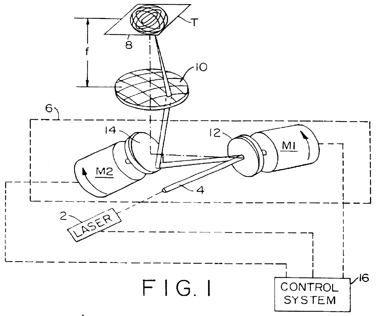
FIG. 1 illustrates the main components of a laser system constructed in accordance with the present invention for use in ablating tissue, shown at T. Thus, the illustrated system includes a laser 2 which produces a continuous laser beam 4. In the preferred embodiment of this invention the laser 2 is a carbon dioxide laser. The continuous laser beam is applied to a laser scanner system, generally shown by box 6, which cyclically scans the beam along two orthogonal axes to cause the beam to trace Lissajous figures, shown generally at 8 in FIG. 1, over the tissue T to be ablated. The laser beam leaving the scanning system 6 first passes through a focussing lens 10 which focusses the laser beam on tissue T.

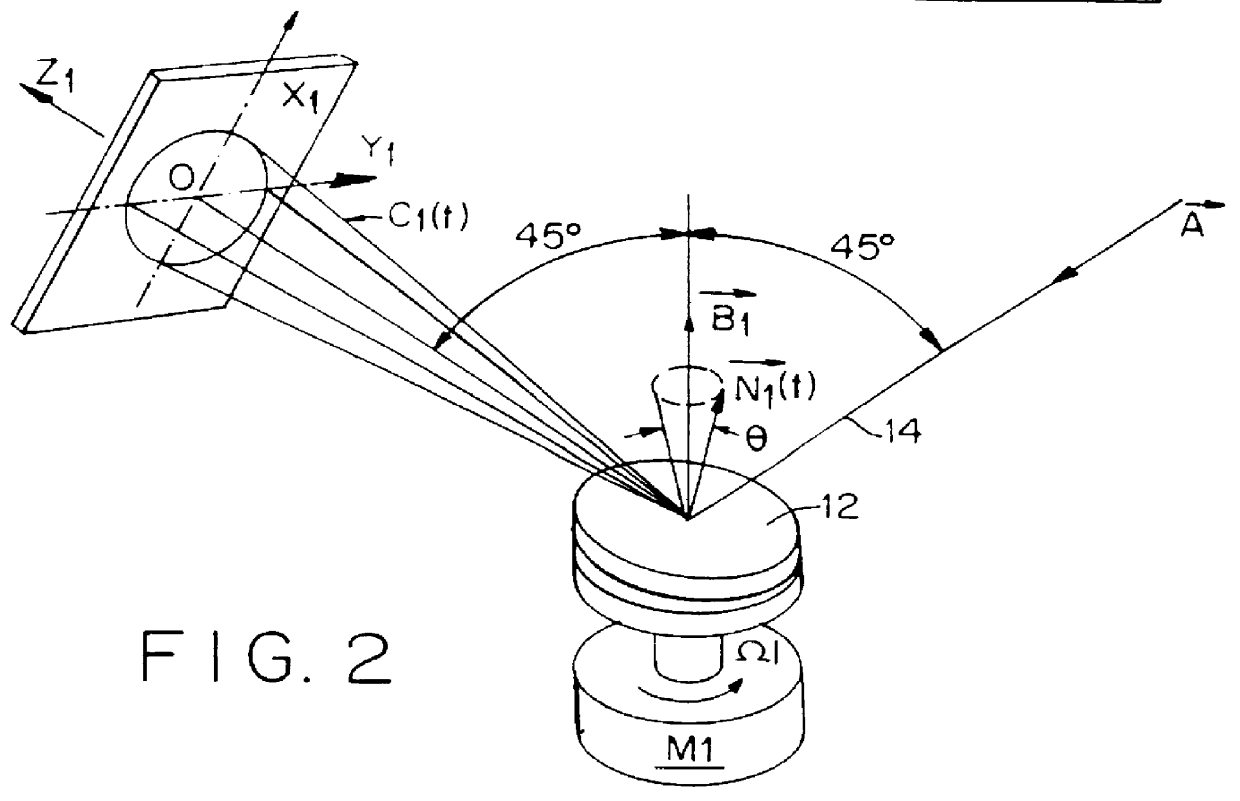
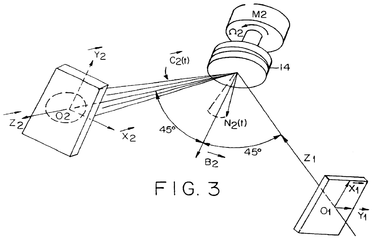
The scanning system 6 includes two mirrors 12, 14, each rotated by a motor M.sub.1. M.sub.2. These mirrors are so located with respect to the laser beam 4 and also to each other to cyclically scan the laser beam along two orthogonal axes, and to cause the ...


PUM

PropertyMeasurementUnit
Timeaaaaaaaaaa
Depthaaaaaaaaaa
Laser radiationaaaaaaaaaa

Abstract

A system for causing uniform ablation of irradiated material of living tissue while not causing damage below a predetermined depth where laser radiation is provided sequentially and continuously in a predetermined pattern is disclosed.

Description

FIELD AND BACKGROUND OF THE INVENTIONThe present invention relates to a system for causing ablation of a target material of living tissue while not causing damage below a predetermined depth. The novel system is particularly useful using a carbon dioxide laser.When using a laser for ablating tissue it is desirable to deliver maximum power density to the tissue to be ablated while minimizing temperature rise in adjacent tissue, particularly in the tissue underlying the tissue to be ablated preventing necrosis in such underlying tissue. Such a temperature rise in underlying tissue may cause thermal damage or carbonization, which generally results in increased scarring and healing time. For this purpose, surgical lasers used for tissue ablation are usually operated with short pulses to deliver high energy in short periods of time. Various pulsing techniques have been developed for this purpose, in which the energy applied for ablation is varied by changing the pulse repetition rate, pu...

Claims


Application Information

Patent Timeline
IPC IPC(8): B23K26/073B23K26/08B23K26/06
CPCB23K26/073B23K26/08B23K26/0884
Inventor ZAIR, ELIEZER
Owner LASER INDS
Why Eureka
Try Eureka