Method of introducing leak detection dye into an air conditioning or refrigeration system including solid or semi-solid fluorescent dyes

a leak detection and air conditioning system technology, applied in the field of leak detection, can solve the problems of inability to distinguish between fluorescence from a leak site and that resulting from inadvertent external contact, the nature of the assembly and charging process creates a risk of spillage or inadvertent contamination of clothing or tools, false leak indications, etc., and achieves the effect of reducing the risk of inadvertent conta

Inactive Publication Date: 2000-11-14
SPECTRONICS
View PDF48 Cites 114 Cited by
  • Summary
  • Abstract
  • Description
  • Claims
  • Application Information

AI Technical Summary

Benefits of technology

For that reason, an objective and advantage of the present invention is a method by which the leak detection dye additive is installed in an air conditioning or other refrigeration system before the system is charged with refrigerant. The leak detection dye is released into the refrigerant immediately after the system is charged and operated, in order to reduce the risk of inadvertent contact of the dye on the outside of the system and yet permit quality control leak testing after charging, and remains in the system to permit subsequent leak detection.
Another objective and advantage of the present invention is a method which allows leak detection dye additive to be installed and stored in a component of the air conditioning system well prior to assembly of the complete system.
Another objective and advanta

Problems solved by technology

There has long been a need to locate leaks in closed refrigeration systems, originally because the loss of refrigerant reduces the cooling capacity of the system, and increasingly because the refrigerants themselves are potential hazardous or deleterious substances when released to the atmosphere.
If dye additive is inadvertently spilled or rubbed on the exterior of the system, it will be difficult to distinguish between fluorescence from a leak site and that resulting from inadvertent external contact.
While care is normally taken to prevent

Method used


Image

  • Method of introducing leak detection dye into an air conditioning or refrigeration system including solid or semi-solid fluorescent dyes
  • Method of introducing leak detection dye into an air conditioning or refrigeration system including solid or semi-solid fluorescent dyes
  • Method of introducing leak detection dye into an air conditioning or refrigeration system including solid or semi-solid fluorescent dyes

Examples


Embodiment Construction

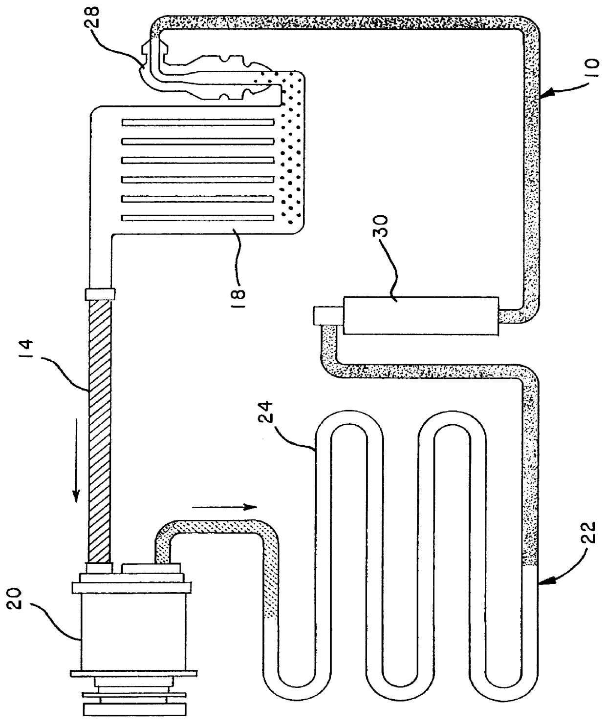
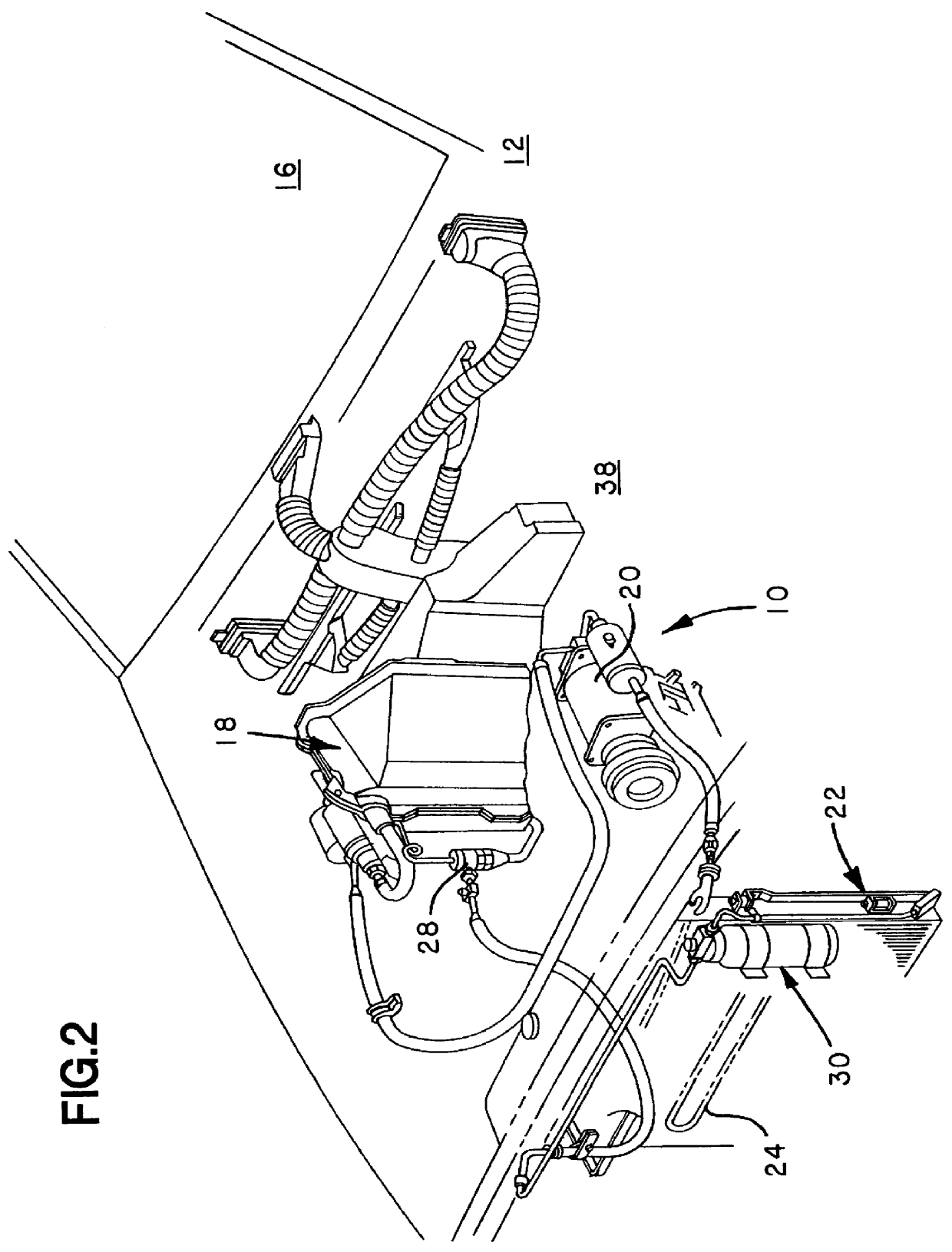
Referring to the drawings, wherein like numerals indicate like elements, FIG. 1 illustrates a basic closed refrigeration circuit 10 of an automobile air conditioner, by which air inside the automobile is cooled and dehumidified. FIG. 2 provides greater detail of the system 10 as it is arranged in an automobile 12.

A refrigerant 14, such as R-12 or more recently R-134a, circulates under pressure in the air conditioning / refrigeration system. In each cycle, the refrigerant is caused to change phase from liquid to gas and back to liquid, absorbing heat from the passenger compartment 16 and releasing heat outside the compartment.

More specifically, the air conditioning system 10 has an evaporator unit 18 where subcooled liquid refrigerant enters and is allowed to expand and absorb heat from warm air of the passenger compartment, causing the refrigerant to vaporize. The warm air of the passenger compartment 16 is connected to the evaporator 18 via ducting, as seen in FIG. 2, such that the c...


PUM


Abstract

PCT No. PCT/US95/04262 Sec. 371 Date Sep. 21, 1995 Sec. 102(e) Date Sep. 21, 1995 PCT Filed Apr. 6, 1995 PCT Pub. No. WO96/07088 PCT Pub. Date Mar. 7, 1996A method of introducing a leak detection dye into a closed refrigeration system through circulation of the refrigerant. A predetermined amount of the leak detection dye, which is soluble in the refrigerant and the system lubricant, is installed in a component of the refrigeration system, such as in a desiccant bag placed in a dehydrator. The leak detection dye may come in various forms including as a leak detection additive having the leak detection dye implanted on and absorbed into a host swatch of a substrate material, as a powder, as a solid pellet of powdered dye concentrate and inert ingredients, or as a slurry. The refrigeration system is assembled, charged and operated, by which the refrigerant and system lubricant flowing through the component, such as a desiccant bag in the dehydrator, and mixes the dye with the refrigerant and system lubricant.

Description

FIELD OF THE INVENTIONThis invention relates generally to the field of detecting leaks in an air conditioning or other refrigeration system and, more particularly, to improved methods of introducing a leak detection dye into the system including the introduction of leak detection dyes into the system in a solid or semi-solid form.BACKGROUND OF THE INVENTIONThere has long been a need to locate leaks in closed refrigeration systems, originally because the loss of refrigerant reduces the cooling capacity of the system, and increasingly because the refrigerants themselves are potential hazardous or deleterious substances when released to the atmosphere. In particular, the production and use of chlorofluorocarbon (CFC) and hydrochlorofluorocarbon (HCFC) refrigerants is scheduled for incremental phaseout, and for recovery and recycling in the interim.Various methods have been used for detecting and locating leaks in a refrigeration system. Since a slow leak of refrigerant is essentially s...

Claims


Application Information

Patent Timeline
IPC IPC(8): G01M3/00G01M3/38G01M3/20G01M3/22
CPCG01M3/38G01M3/228G01M3/20F25B2500/222
Inventor COOPER, B. WILLIAMLU, LING
Owner SPECTRONICS
Why Eureka
Try Eureka