Fuel hose and method of its production

a technology of fuel hoses and hoses, which is applied in the direction of pipes, plasma techniques, synthetic resin layered products, etc., can solve the problems of low bonding affinity of ordinary fluororesin with other structural materials, risk of partial delamination of tubular fluororesin inner ply from outer ply, and inability to firmly bond two plies using an adhesive alone. , to achieve the effect of reducing the cost of the fuel hose, prolonging the servi

Inactive Publication Date: 2003-04-22
SUMITOMO RIKO CO LTD
View PDF28 Cites 11 Cited by
  • Summary
  • Abstract
  • Description
  • Claims
  • Application Information

AI Technical Summary

Benefits of technology

This invention has for its object to provide a fuel hose having a sufficiently high initial bond strength of not less than 1.2 N / mm between the fluororesin inner ply and the thermoplastic resin or other ply, which is easy to manufacture and free from problems in work safety and cost, a method for production of the hose, and a vacuum plasma apparatus for use in the method.

Problems solved by technology

The reason for this is that because the bonding affinity of ordinary fluororesin for other structural materials is very low, said two plies cannot be firmly bonded using an adhesive alone.
This is because, as far as the fuel hose for use typically in the fuel system of a motor vehicle is concerned, unless it has an initial bond strength value not below the above-mentioned level under the service conditions where a fuel such as gasoline flows down it, there is the risk of partial delamination of the tubular fluororesin inner ply from the outer ply.
However, the above surface-modified fluororesin materials have various disadvantages.
Thus, the fuel hose fabricated using the first-mentioned fluororesin (1) having a sodium metal complex-modified surface suffers aging in adhesion.
This loss of adhesion is particularly remarkable when the hose is exposed to ultraviolet radiation.
Moreover, since the above surface modification with a sodium metal complex requires the step of immersing fluororesin in a solution of the sodium metal complex and subsequently washing it, this technology has the drawback of being a time-consuming, complicated process.
Moreover, the sodium metal complex solution is hazardous to health.
The latter fluororesin having a sputtered surface (2) does not provide for sufficient adhesion when the flowability of the adhesive is low and has the additional disadvantage that the recesses and projections formed by sputtering are easily evened out by friction.
Therefore, in the manufacture of a fuel hose using the sputtered fluororesin material, its handling calls for sufficient care and this consideration detracts from the efficiency of production of the fuel hose.
Furthermore, these prior art fluororesins have the common problem that they provide for only poor adhesion when a thermoplastic resin or the like is directly bonded thereto without the aid of an adhesive.
Actually, however, the conventional surface-modified fluororesin materials provide for only poor adhesion by the thermal fusion technique, with the result that the above-mentioned inherent advantages of the technique cannot be exploited.
However, only a few kinds of fluororesins are available to which the surface modification by this technique can be successfully applied and, moreover, the technique has the disadvantage that the expression of adhesion cannot be uniformly obtained over a spectrum of fluororesins each having its own useful performance characteristics.
Furthermore, the range of said F / C ratio and of said O / C ratio is very limited so that an elaborate, delicate control technology is essential for converging the surface of any fluororesin into said narrow ranges of atomic ratios, with the result that the production is inevitably complicated.
Thus, because of the lack of sufficient adhesion of the prior art surface-modified fluororesins, fuel hoses manufactured using them are not possessed of the initial bond strength or green bond strength necessary for service.
Moreover, the fuel hoses manufactured by the conventional production technologies are not free from problems in the aspects of work safety, production efficiency and cost.

Method used


Image

  • Fuel hose and method of its production
  • Fuel hose and method of its production
  • Fuel hose and method of its production

Examples


example 6

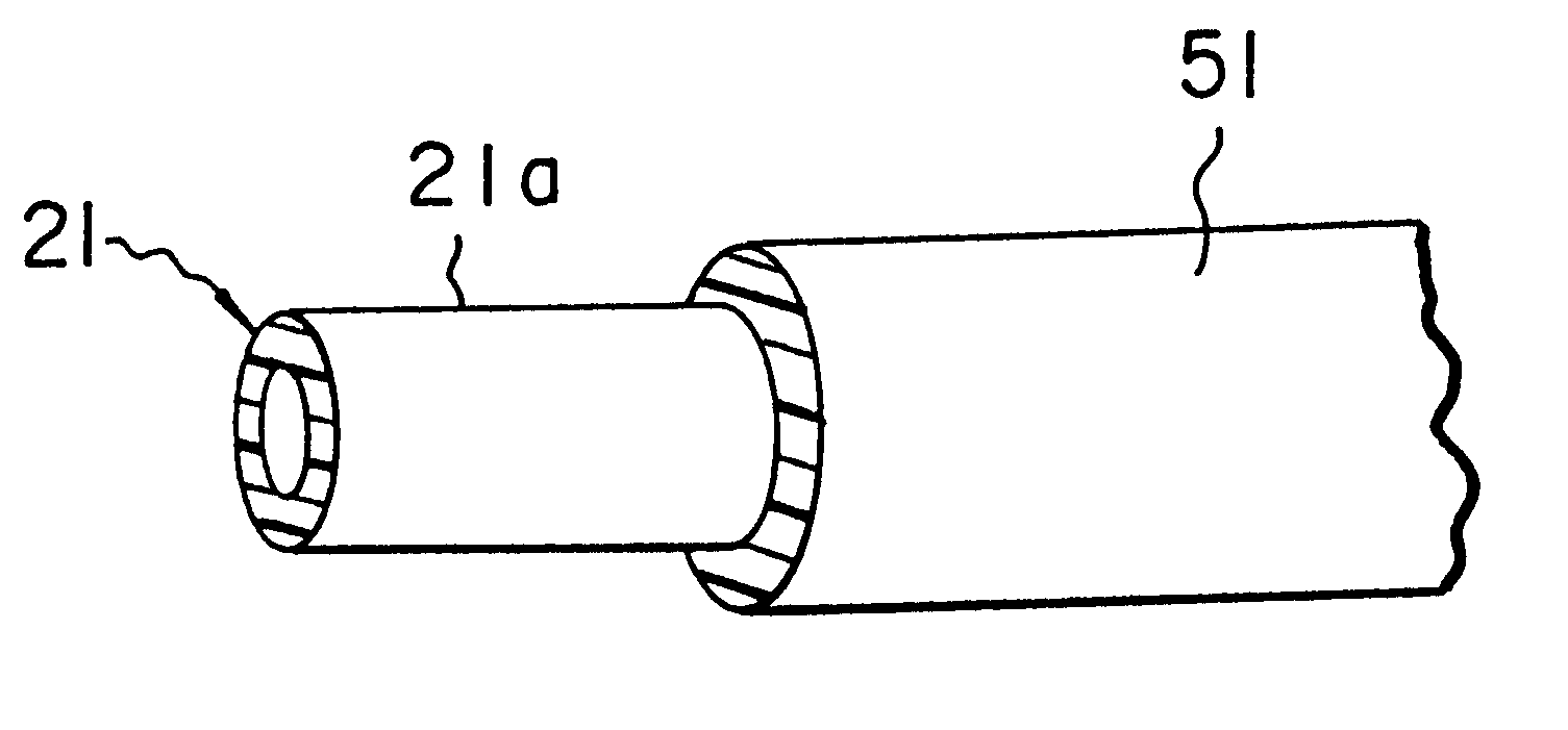
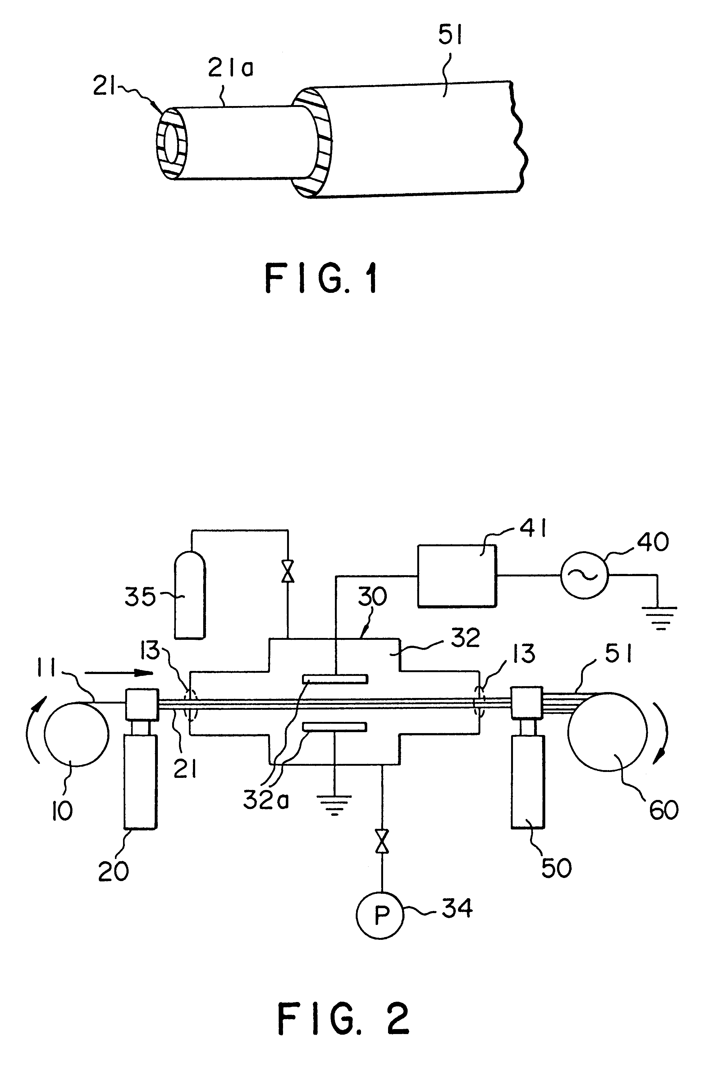
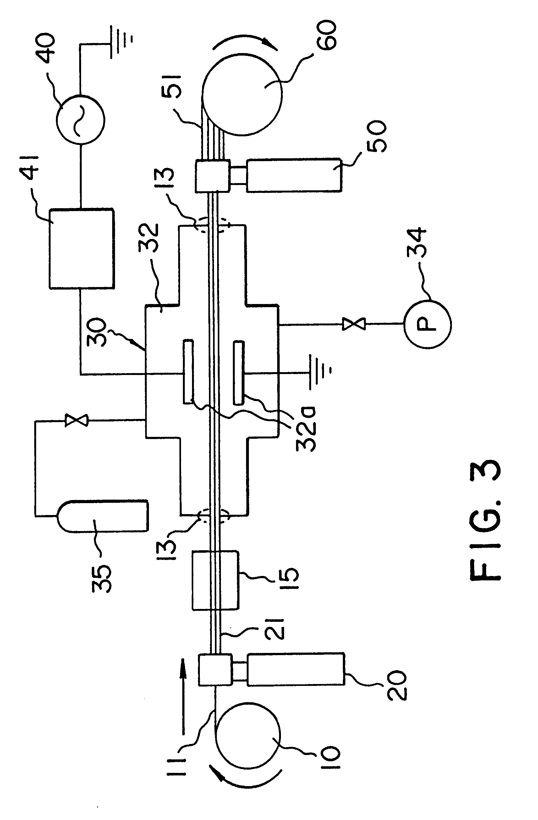
Using a vacuum plasma apparatus illustrated in FIG. 2 for plasma treatment, ETFE for the tubular fluororesin inner ply and ECO for the outer ply to be formed on the peripheral surface of said inner ply, a fuel hose was fabricated. In this production process, Ar gas was used as the electrical discharge gas, the degree of vacuum was set at 0.05 Torr, and the thickness of the ECO ply was controlled at 2 mm. After extrusion of the outer ply from the extruder 50, the laminate was taken up on the mandrel takeup 60 and the ECO ply 51 was then vulcanized at 160.degree. C. for 45 minutes. Otherwise the procedure of Examples 1-5 was repeated to provide a fuel hose of Example 6.

examples 7 and 8

Except that CTFE was used as the molding material for the tubular fluororesin inner ply and the electrical discharge gases and degrees of vacuum shown below in Table 2 were employed, fuel hoses were fabricated in otherwise the same manner as Examples 1-5.

TABLE 2 Electrical Degree of vacuum Example discharge gas (Torr) 7 N.sub.2 0.1 8 N.sub.2 0.05

examples 9-14

Except that FEP was used as the molding material for the tubular fluororesin inner ply and the electrical discharge gases and degrees of vacuum shown below in Table 3 were employed, fuel hoses were fabricated in otherwise the same manner as Examples 1-5.

TABLE 3 Electrical Degree of vacuum Example discharge gas (Torr) 9 Ar 0.1 10 Ar 0.05 11 N.sub.2 0.3 12 N.sub.2 0.1 13 N.sub.2 0.05 14 Ar + N.sub.2 0.05 15 Ar 0.05


PUM

PropertyMeasurementUnit
volume resistivityaaaaaaaaaa
speedaaaaaaaaaa
diameteraaaaaaaaaa

Abstract

The fuel hose of this invention is a fuel hose comprising a tubular fluororesin inner ply and, as laminated onto the peripheral surface thereof, a thermoplastic resin or rubber outer ply, the tubular fluororesin inner ply having been molded from a fluororesin with an F / C ratio, i.e. ratio of the number of fluorine atoms (F) to the number of carbon atoms (C), of not greater than 1.6 and the peripheral surface layer of the fluororesin inner ply having been modified into the following treated layer (A).(A) a layer with a distribution of oxygen atoms and having an F / C ratio, i.e. ratio of the number of fluorine atoms (F) to the number of carbon atoms (C), of not greater than 1.12 and an O / C ratio, i.e. ratio of the number of oxygen atoms (O) to the number of carbon atoms (C), of not less than 0.08.In this fuel hose of the invention, the treated layer (A) of the tubular fluororesin inner ply has a remarkably increased adhesive affinity for thermoplastic resin and rubber, with the result that the bond strength between the tubular fluororesin inner ply and the thermoplastic resin or rubber outer layer is as high as not less than 1.2 N / mm.

Description

TECHNICAL FIELDThis invention relates to a fuel hose for use in the fuel system of a motor vehicle or other equipment, particularly a fuel hose consisting of a tubular fluororesin inner ply and a thermoplastic resin or rubber outer ply with a high inter-ply bond strength, a method of producing it, and a vacuum plasma apparatus for use in said method.PRIOR ARTGenerally the fuel hoses used in the fuel systems of cars and other equipment have multi-ply structures consisting of various rubber and resin plies or layers. Among such multi-ply fuel hoses, the two-ply fuel hose consisting of a tubular fluororesin inner ply and a thermoplastic resin or rubber outer ply laminated on the peripheral surface of said tubular inner ply is in prevalent use. The rationale is that, being not only resistant to the common corrosive agents such as chemicals and gasoline but also resistant to the sour gasoline which forms on oxidation of gasoline (sour gasoline resistance), fluororesin is generally regard...

Claims


Application Information

Patent Timeline
Patent Type & Authority Patents(United States)
IPC IPC(8): B29C47/02B32B1/00B29C59/00B29C47/06B32B1/08B29C59/14B32B27/08B32B27/34B32B27/28F16L11/04B29C48/09B29C48/151B29C48/21B29D23/00B32B25/08B32B25/14F16L11/12
CPCB29C47/0023B29C47/021B29C47/065B29C59/142B29D23/001B32B1/08B32B25/08B32B25/14B32B27/08B32B27/28B32B27/34B32B38/0008F16L11/045F16L11/125F16L11/127B29C47/0052Y10T428/1393B29K2021/00B29K2027/12B29K2077/00B29L2009/00B29L2023/005B32B2319/00B32B2327/12F16L2011/047Y10T428/1321Y10T428/1366Y10T428/1314B29C48/09B29C48/0016B29C48/151B29C48/21Y10T428/31743B29D23/00F16L11/04B32B27/16B32B2597/00B32B2307/202B32B2309/105B32B27/304B32B27/322
Inventor YOKOE, KATSUHIKOKATO, KAZUHIROMURAKAMI, KOYODAIKAI, EIICHIITO, HIROAKI
Owner SUMITOMO RIKO CO LTD
Why Eureka
Try Eureka