Car electronic control system and method for controlling the same

a technology of electronic control system and control system, which is applied in the direction of electric controllers, anti-theft devices, instruments, etc., can solve the problems of inability to realize sufficiently reduced current consumption, and achieve the effect of suppressing current consumption, minimizing the time duration of operation of the mpu, and suppressing current consumption in the sleep mod

Inactive Publication Date: 2003-12-02
HITACHI LTD +1
View PDF35 Cites 34 Cited by
  • Summary
  • Abstract
  • Description
  • Claims
  • Application Information

AI Technical Summary

Benefits of technology

With such an arrangement as mentioned above, since the need for provision of an oscillation circuit to a circuit for judgement of whether to be a wake-up signal can be eliminated, current consumption in the sleep mode can be suppressed. Further, even after the MPU starts its operation, the MPU is not shifted to a usual control operation until the MPU judges that the wake-up signal is normal. Thus, as soon as the MPU judges that the input signal is the noise signal, the MPU can be immediately shifted to the sleep mode, whereby the time duration of operation of the MPU can be minimized and current consumption can be suppressed even in a high noise state.

Problems solved by technology

In this way, in the prior art, the low-frequency oscillation circuit is operated even in the sleep mode so that, even when it is unnecessary to wake up the system, the entire system is put in the usual operation, thus disabling realization of sufficiently reduced current consumption.

Method used


Image

  • Car electronic control system and method for controlling the same
  • Car electronic control system and method for controlling the same
  • Car electronic control system and method for controlling the same

Examples


Embodiment Construction

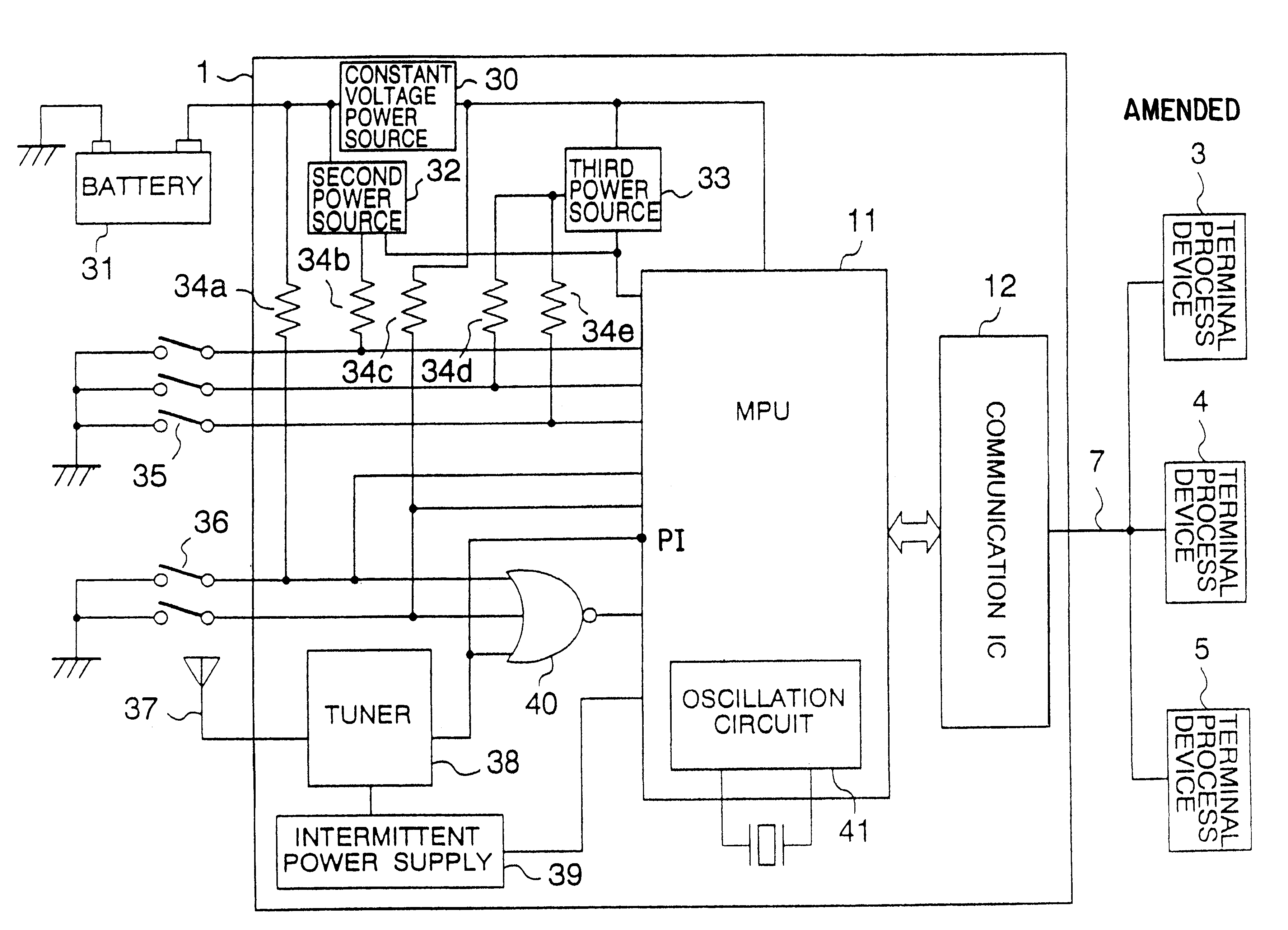
There is shown a block diagram of an arrangement of an electronic control system in accordance with a first embodiment of the present invention in FIGS. 5 and 6, wherein FIG. 5 is a block diagram of details of a central processing unit (CPU) 1 in FIG. 6. In FIGS. 5 and 6, terminal processors 3, 4 and 5 are connected to each other by a multiplex communication line 7 so that input information on switches connected to the respective terminal processors or output information on lamps or motors connected thereto are transferred on a multiplex communication basis to carry out entire control thereover. In FIG. 5 showing the configuration of the central processing unit 1, a battery 31 supplies power to the central processing unit and also to respective devices of the entire vehicle including the terminal processors 3, 4 and 5. A second power supply circuit 32 switches between supply or non-supply of a voltage of the battery to circuits positioned downstream thereof on the basis of a signal ...


PUM


Abstract

A car remote control system utilizing a signal in the form of electromagnetic wave or infrared ray called `keyless entry`. When receiving a predetermined wake-up signal, an MPU is once operated even when the received input signal is a noise signal to perform only judging operation of whether or not the input signal is normal. Only when judging that the input signal is a normal wake-up signal, the MPU controllably causes an electronic circuit to be shifted to a usual operation mode. When judging that the input signal is the noise signal prior to full input of the tuner signal, the MPU immediately shifts to a sleep mode. Thereby current consumption of an electronic control circuit can be suppressed.

Description

BACKGROUND OF THE INVENTIONThe present invention relates to an electronic control system for performing remote control over a car or vehicle with use of a radio signal such as radio wave or infrared ray, called keyless entry and more particularly, to an electronic control system for car remote control which switches between its sleep and operational modes as well as to a multiplex communication system employed for the electronic control system.As a system for controlling supply of power to this type of electronic control system not having a remote control function, it is known as disclosed in JP-A-63-71451 to stop a terminal clock when power supply is unnecessary.Also disclosed in JP-A-5-32142 is a system, when a microcomputer-controlled system is put in its sleep mode, for also causing a power supply for a watch dog timer to be automatically turned OFF, thus realizing reduction in its current consumption. Further, when it is desired to provide a remote control function to the elect...

Claims


Application Information

Patent Timeline
Patent Type & Authority Patents(United States)
IPC IPC(8): B60R16/02G07C9/00B60R16/03
CPCB60R16/0315B60R2016/0322G07C9/00182G07C2009/00261G07C2009/00769H04Q9/00Y02T10/92
Inventor YOSHIDA, TATSUYAKON'I, MITSURU
Owner HITACHI LTD
Why Eureka
Try Eureka