Apparatus and method for self adjusting downlink signal communication

a technology of mud pulse and signal communication, which is applied in the direction of survey, instruments, borehole/well accessories, etc., can solve the problems of unavoidable dispersion, mud pulse attenuation and dispersion, and methods that are difficult to use in measurement-while-drilling ("mwd") operations

Inactive Publication Date: 2004-08-24
BAKER HUGHES INC
View PDF14 Cites 18 Cited by
  • Summary
  • Abstract
  • Description
  • Claims
  • Application Information

AI Technical Summary

Benefits of technology

The present invention is a self adjusting communication link incorporating a mud-pulse telemetry system for controlling downhole devices. A main pump operating at a substantially constant flow rate pumps mud from a source thereof, such as a mud pit. The bulk of the pumped mud goes downhole to maintain adequate circulation through the wellbore. A bypass conduit or path is provided with a fluid flow control device that is controlled by a control unit or circuit. The amplitude and duration of the mud pulses are controlled by pulsing the flui

Problems solved by technology

However, these methods are difficult to use in measurement-while-drilling ("MWD") operations because of the necessity of maintaining an adequate mud flow for drilling operations and of the noise associated with the mud flow and with the rotating drillstring.
This is fraught with problems because of the wear and tear on the mud pumps from constant starting and stopping.
A major accompanying problem is that the mud pulses attenuate and disperse as they propagate through the drilling mud.
This dispersion is unavoidable and is caused by various mechanisms, including viscous dissipation in the drilling mud as well as frictional energy loss at the borehole walls.
This problem is exacerbated with increasing depth of the well

Method used


Image

  • Apparatus and method for self adjusting downlink signal communication
  • Apparatus and method for self adjusting downlink signal communication
  • Apparatus and method for self adjusting downlink signal communication

Examples


Embodiment Construction

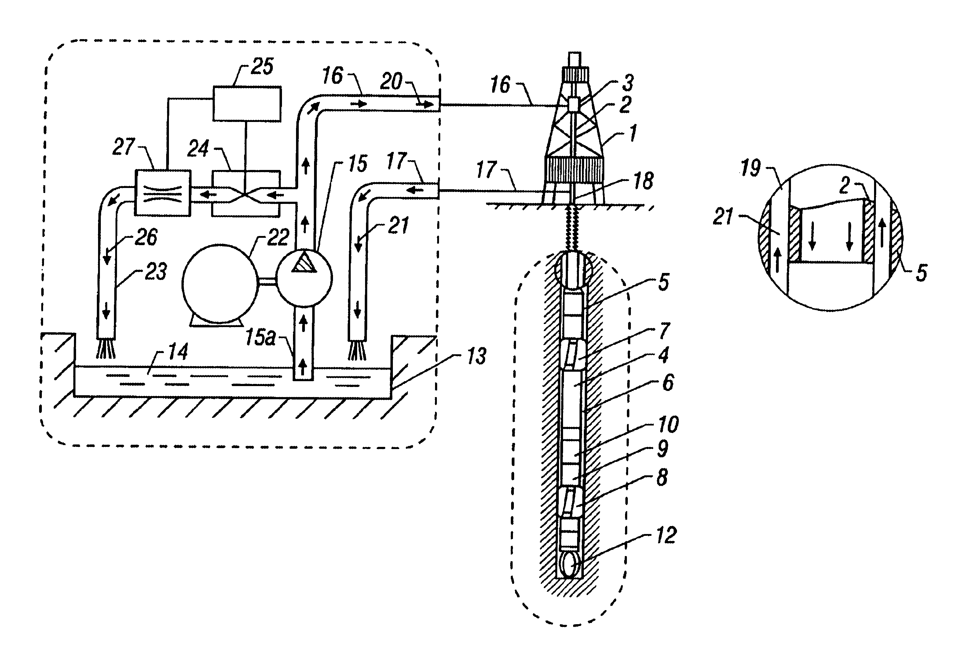
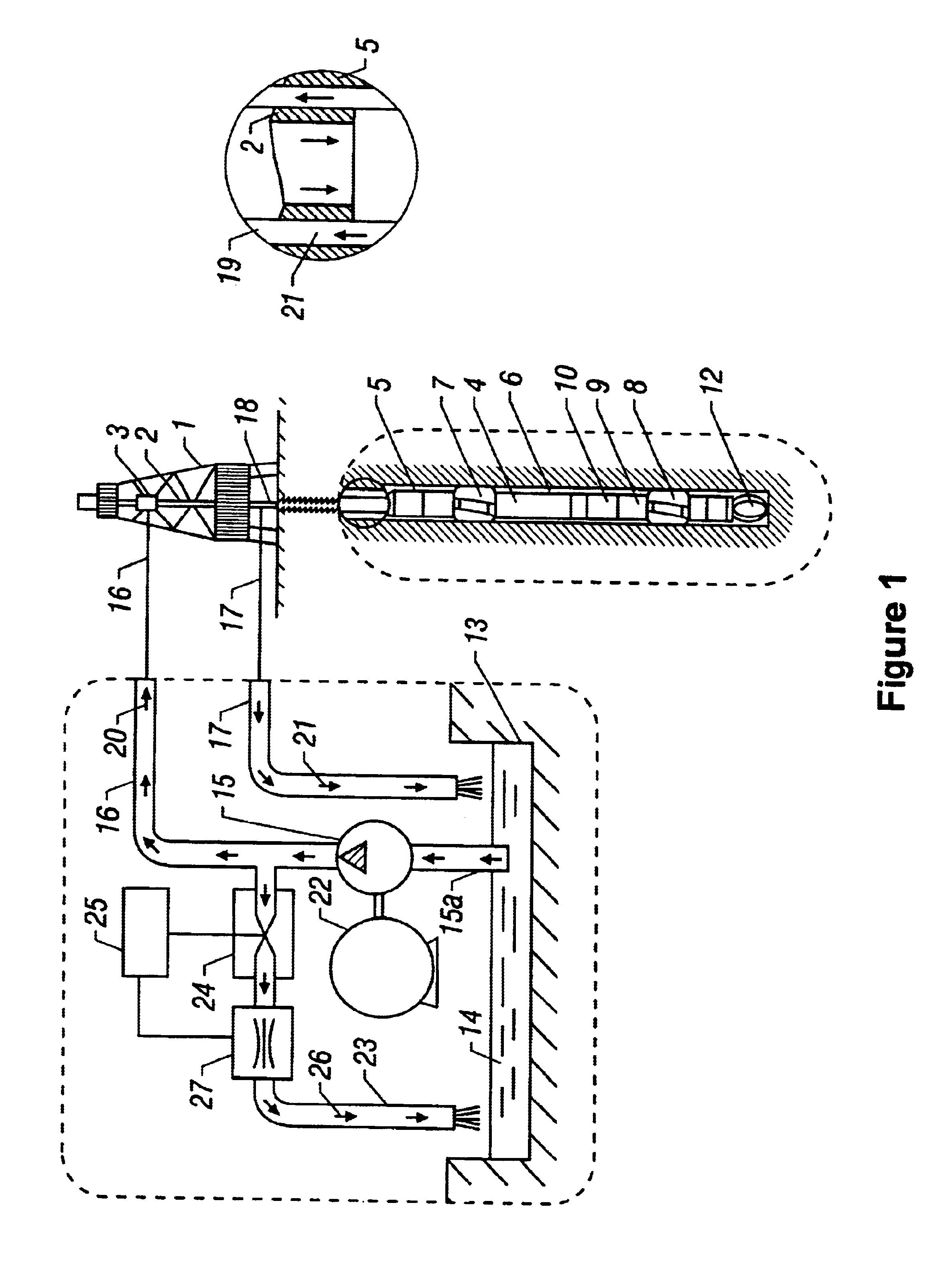
The present invention is best understood by reference to the FIGS. 1-3. FIG. 1 is a schematic illustration of a drilling rig 1 that has a swivel head 3 to which is attached the drill string 2. At the bottom of the drill string 2 is a drilling tool 4. The drilling tool 4 is conveyed in the borehole 5 and includes a housing 6. Attached to the housing are stabilizers 7, 8 for stabilizing for reducing vibrations and a non-rotating sleeve 9 with ribs 10 that can be extended and retracted in a controlled fashion. The ribs are used to control the direction of drilling of the tool. The non-rotating sleeve 9 maintains a substantially fixed orientation in the borehole, independent of the rotation of the drill string 2. The drilling tool 4, together with the drill head 12 can be caused to rotate by using the drill string 2.

FIG. 1 also shows a mud pit 13 in which there is a supply of drilling mud 14. A mud pump 15 has an inlet pipe 15a dipping into the mud and a main pipe 16 connected to the sw...


PUM


Abstract

An apparatus for sending signals downhole during drilling operations uses a main pump to pump mud from a mud pit at a substantially constant flow rate. The bulk of the pumped mud goes downhole to maintain adequate circulation for the drill bit. A bypass pipe is provided with a shut-off valve that is controlled by an electronic controller. By pulsing the opening and closing of the shut-off valve, the volumetric flow downhole is pulsed. The pulse amplitude and duration can be controlled. These pulses in the flow rate are detected by a suitable downhole device such as a flow rate measurement device, a pressure detector or a turbine. The initial "wake-up" pulse is made long enough so that the detection device downhole is always able to detect it. Subsequent to this wake-up pulse, adjustments are made to the pulse duration, in steps of about 2 seconds, for the smallest pulse period that is detectable downhole. In addition, the amplitude of the pulses is also controlled by regulating the maximum flow through the shut-off valve. The pulses are modulated by a binary sequence of numbers corresponding to the data to be transmitted.

Description

FIELD OF THE INVENTIONThe invention relates to the control of downhole drilling equipment by a mud pulse telemetry system, and particularly to an automatic adjustment of the pulse amplitude and duration to account for the attenuation of signals at increased depth.BACKGROUND OF THE INVENTIONWell bores or boreholes are drilled using a drilling assembly (also referred to as the "bottom hole assembly" or "BHA") carrying a drillbit at its bottom hole end. The BHA includes a variety of sensors to gather information about the wellbore and subsurface formations along with associated processing circuits and microprocessors. Data and signals are transmitted from the surface to control the operation of devices in the BHA. Such devices include motors, hydraulic devices, etc. A number of signal transmission methods have been used to send signals from the surface to a receiver in the BHA. In one such method, an acoustic signal carried by the mud or by the drillstring is used. Electromagnetic sign...

Claims


Application Information

Patent Timeline
IPC IPC(8): G08B21/00E21B21/08E21B41/00E21B47/18
CPCE21B21/08E21B41/00E21B47/18E21B47/24
Inventor GRUENHAGEN, HARTMUT H.
Owner BAKER HUGHES INC
Why Eureka
Try Eureka