Methods and devices to design and fabricate surfaces on contact lenses and on corneal tissue that correct the eye's optical aberrations

a technology of corneal tissue and contact lens, which is applied in the field of methods and devices to design and fabricate surfaces on contact lenses and on corneal tissue that correct the eye's optical aberration, and achieves the effect of improving the vision of patients

Inactive Publication Date: 2005-10-18
MAGNANTE PETER C
View PDF14 Cites 42 Cited by
  • Summary
  • Abstract
  • Description
  • Claims
  • Application Information

AI Technical Summary

Benefits of technology

[0019]Conventional spectacles and contact lenses are able to correct the visual acuity of most people to 20 / 20 or better. For these individuals, the most significant refractive errors are those caused by the so-called lowest order optical aberrations, namely defocus, astigmatism and prism. However, there are many people with normal retinal function and clear ocular media who cannot be refracted to 20 / 20 acuity with conventional ophthalmic lenses because their corneal surfaces are extraordinarily irregular. In this group are patients with severe irregular astigmatism, keratoconus, corneal dystrophies, post penetrating keratoplasty, scarring from ulcerative keratitis, corneal trauma with and without surgical repair, and sub-optimal outcome following refractive surgery. The eyes of these people have abnormal amounts of higher order or irregular optical aberrations. An objective of the invention is to improve the vision of these patients. A further objective is to provide the best vision possible to individuals with ordinary near and farsightedness and astigmatism. To achieve these objectives, methods and devices are described that are used to design and fabricate modified surfaces on contact lenses or on corneal tissue that correct the eye's optical aberrations beyond defocus and astigmatism.

Problems solved by technology

However, there are many people with normal retinal function and clear ocular media who cannot be refracted to 20 / 20 acuity with conventional ophthalmic lenses because their corneal surfaces are extraordinarily irregular.

Method used


Image

  • Methods and devices to design and fabricate surfaces on contact lenses and on corneal tissue that correct the eye's optical aberrations
  • Methods and devices to design and fabricate surfaces on contact lenses and on corneal tissue that correct the eye's optical aberrations
  • Methods and devices to design and fabricate surfaces on contact lenses and on corneal tissue that correct the eye's optical aberrations

Examples


Embodiment Construction

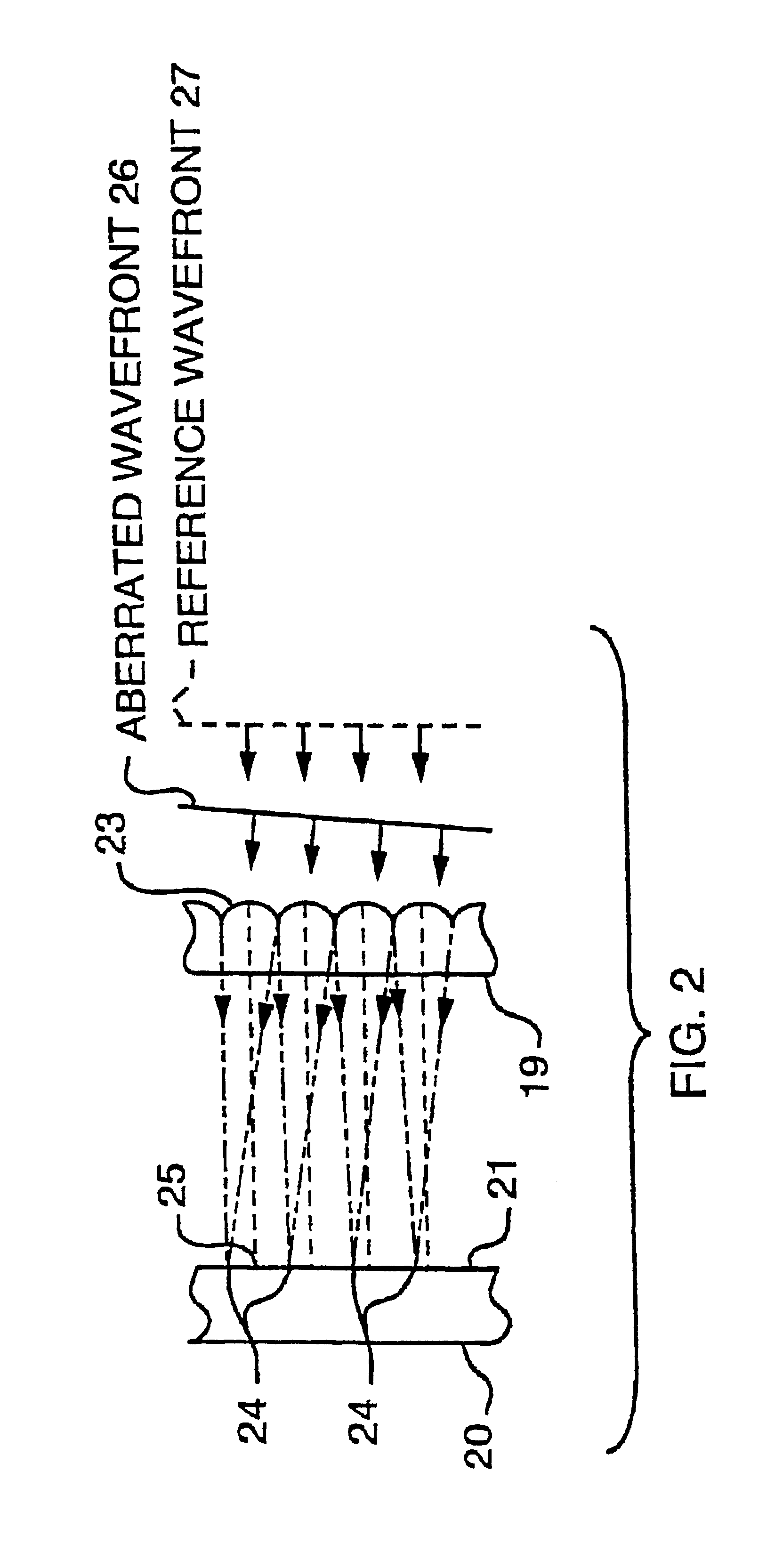
[0024]4.1 Wavefront Sensor for Measuring the Eye's Optical Aberrations

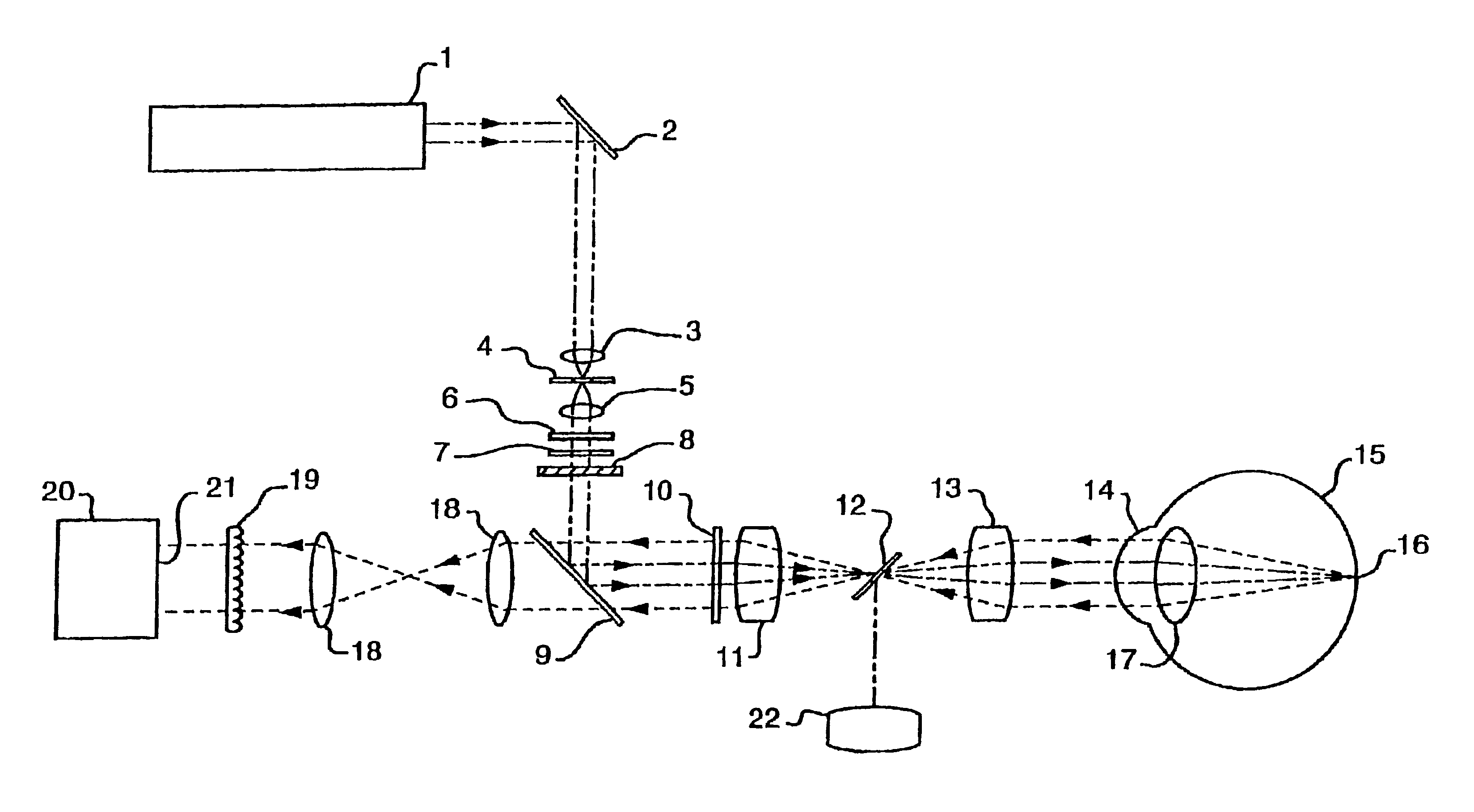
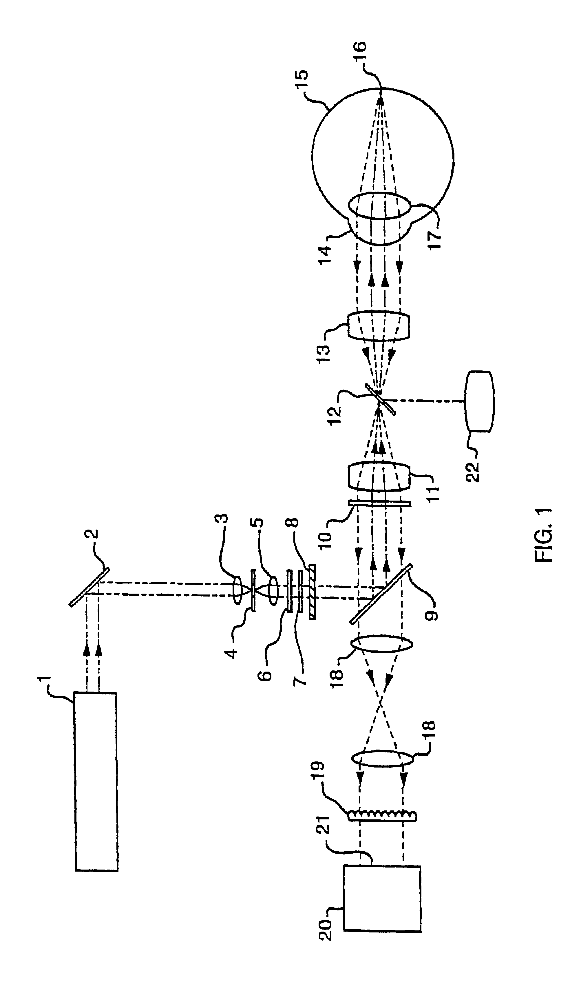
[0025]A schematic drawing of a wavefront sensor which has been modified to measure the eye's optical aberrations is shown in FIG. 1. The design and operating principles of the subassemblies of the wavefront sensor are explained in detail below.

[0026]4.1.1 Projection System

[0027]In order to reduce bothersome “speckle” from coherence effects from conventional laser sources, non-coherent optical sources are preferred. Thus, source 1 can be anyone of the following: laser diode operating below threshold, light emitting diode, arc source, or incandescent filament lamp. The source beam is deflected by fold mirror 2, and focused by microscope objective lens 3 onto a small pinhole aperture 4 having a diameter typically in the range from 5 to 15 microns. Another lens 5 collimates the beam which next passes through polarizer 6 and then through aperture stop 7. Typically this stop restricts the beam diameter to about 2 mm or ...


PUM

PropertyMeasurementUnit
diameteraaaaaaaaaa
diametersaaaaaaaaaa
diameteraaaaaaaaaa

Abstract

Methods and devices are described that are needed to design and fabricate modified surfaces on contact lenses or on corneal tissue that correct the eye's optical aberrations beyond defocus and astigmatism. The invention provides the means for: 1) measuring the eye's optical aberrations either with or without a contact lens in place on the cornea, 2) performing a mathematical analysis on the eye's optical aberrations in order to design a modified surface shape for the original contact lens or cornea that will correct the optical aberrations, 3) fabricating the aberration-correcting surface on a contact lens by diamond point turning, three dimensional contour cutting, laser ablation, thermal molding, photolithography, thin film deposition, or surface chemistry alteration, and 4) fabricating the aberration-correcting surface on a cornea by laser ablation.

Description

1. BACKGROUND OF THE INVENTION[0001]1.1 Measurements of the Eye's Aberrations[0002]There are several objective optical techniques that have been used to measure the wavefront aberrations of the eye. The aberroscope, which is disclosed by Walsh et al. in the Journal of the Optical Society of America A, Vol.1, pp. 987-992 (1984), projects a nearly collimated beam into the eye which is spatially modulated near the pupil by a regular grid pattern. This beam images onto the retina as a small bright disk which is modulated by the dark lines of the grid pattern. Since the eye's pupillary aberrations distort the retinal image of the grid pattern, measurements of the distortions on the retina reveal the pupillary aberrations.[0003]The spatially resolved refractometer, which is disclosed by Webb et al. in Applied Optics, Vol. 31, pp. 3678-3686 (1992), projects a small diameter collimated beam through the eye's pupil. Instead of being spatially modulated by a physical grid as with the aberrosc...

Claims


Application Information

Patent Timeline
Patent Type & Authority Patents(United States)
IPC IPC(8): A61B3/14A61B3/103A61B3/15A61B3/10G01M11/02G02C7/04G02C13/00
CPCA61B3/1015
Inventor MAGNANTE, PETER C.
Owner MAGNANTE PETER C
Why Eureka
Try Eureka