
Remote reservoir resistivity mapping

a reservoir resistivity and remote technology, applied in the field of geophysical prospecting, can solve the problems of obscuring dhi and avo signatures, unable to detect seismicity, and unable to achieve remote mapping and analysis of hydrocarbon reservoirs at depth,

Inactive Publication Date: 2008-05-20
EXXONMOBIL UPSTREAM RES CO
View PDF11 Cites 41 Cited by
  • Summary
  • Abstract
  • Description
  • Claims
  • Application Information

AI Technical Summary

Problems solved by technology

Remote mapping and analysis from the surface of the earth of hydrocarbons reservoired at depth remains a difficult technical task.
Seismic detection difficulties arise in part from the fact that the mechanical properties of reservoirs, to which the seismic probe responds, are often only slightly modified when hydrocarbons replace formation waters, especially in the case of oil.
Subtle mechanical effects related to seismic wave propagation and reflection can mask DHI and AVO signatures or even produce misleading signatures.
For example, low gas saturation in water sands can produce false seismic DHIs.
Because of such effects, drill-well success rates are too low and exploration costs are too high in many basins.
Acquiring this knowledge is problematic using only seismic data.
However, increased formation resistivity alone may not uniquely indicate hydrocarbons.
However, it would also have low electrical resistivity and hence would be a high-risk drill-well prospect.
However, there is no existing technology for remotely measuring reservoir formation resistivity from the land surface of the seafloor at the vertical resolution required in hydrocarbon exploration and production.
Direct exploration for hydrocarbons using surface-based electromagnetic imaging has been attempted since the 1930s, but with little commercial success.
This lack of success is due to the low spatial resolution and the ambiguous interpretation results of current electromagnetic methods, when applied in stand-alone and spatially undersampled ways to the geological imaging problem.
The vertical resolution of such electromagnetic waves is relatively insensitive to bandwidth, unlike the seismic case, but is very sensitive to the accuracy and precision of phase and amplitude measurements and to the inclusion of constraints from other data.
That is, the unconstrained geophysical electromagnetic data inverse problem is mathematically ill posed, with many possible geologic structures fitting electromagnetic data equally well.
Consequently, the vertical resolution of unconstrained electromagnetic imaging is typically no better than 10 percent of depth.
All five methods suffer from the vertical resolution limitation of approximately 10% of depth cited above, which makes them unsuitable for direct reservoir imaging except for unusually thick reservoirs.
This resolution limitation results from one or more of the following deficiencies in each method: (1) lack of means to focus the electromagnetic input energy at the target reservoir; (2) spatial undersampling of the surface electromagnetic response fields; (3) measurement of only a few components (usually one) of the multi-component electromagnetic surface fields that comprise full tensor electromagnetic responses at each reservoir (except for WEGA-D / PowerProbe); (4) data processing using 1-D, 2-D, or pattern recognition algorithms rather than full 3-D imaging methods; and (5) lack or paucity of explicit depth information and resistivity parameter values incorporated into the data processing to constrain the inversion results.
Another serious limitation in these five methods is their use of high-impedance contact electrodes and connecting wires, with greater than 1 Ohm total series resistance, to transmit the source current into the subsurface.
High output impedance severely limits the electrical current at the reservoir depth, which in turn reduces the strengths of the surface electromagnetic responses to the subsurface reservoir for a given source power.
Current limitation due to high-impedance sources also results in reduced depths of exploration, especially in electrically conductive sedimentary basins.
However, ring electrodes described by Mogilatov and Balashov do not contain discussions of, much less calculations for, the optimum electrode dimensions needed to maximize the vertical electric field or current density at the target (reservoir) depth.
However, Verma and Sharma restrict their discussion to subsurface conducting layers, and do not include unipole or concentric ring dipole arrays in their calculations.
Natural-source methods such as that of Hoversten et al. lack the vertical resolution required for direct imaging of resistive hydrocarbon reservoirs, because they measure the earth's response to the flow of horizontal subsurface electrical currents that are insensitive to regions of increased resistivity.
However, there is no existing remote (surface-based) electromagnetic method for measuring both the separate vertical and horizontal resistivities of a reservoir interval at depth.

Method used


Image

  • Remote reservoir resistivity mapping
  • Remote reservoir resistivity mapping
  • Remote reservoir resistivity mapping

Examples


Embodiment Construction

[0032]The invention is a method whereby the average vertical and horizontal formation resistivities of a hydrocarbon reservoir are remotely mapped from the land surface or the seafloor, using low-frequency electromagnetic waves constrained by seismic depth imaging and other a priori information about the subsurface. The invention overcomes the electromagnetic low vertical resolution problem by a combination of data acquisition and processing steps that are targeted at mapping the resistivity of a previously located or prospective reservoir.

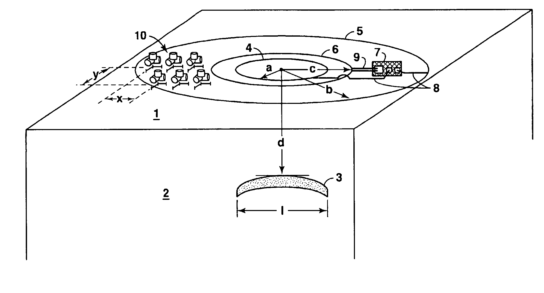
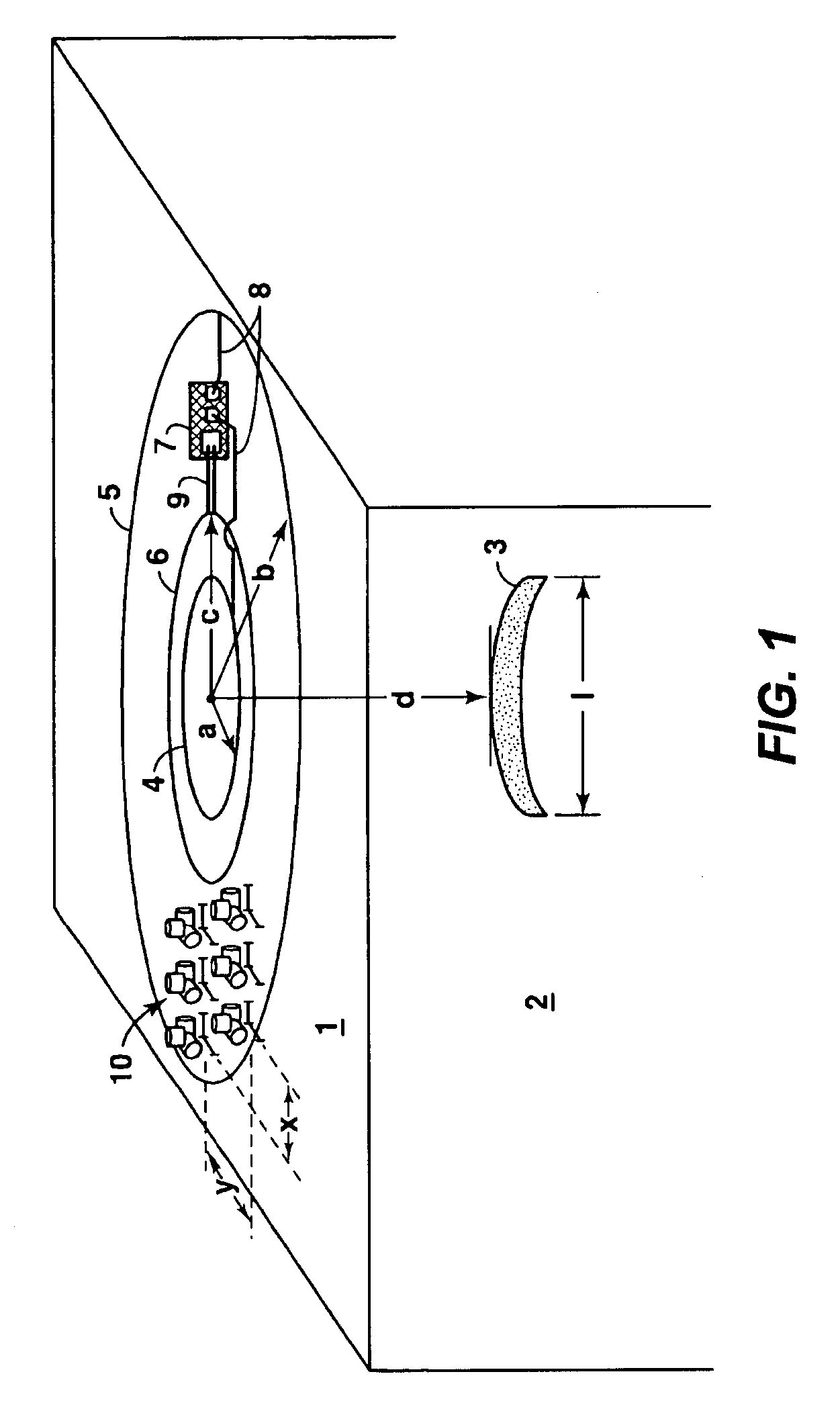
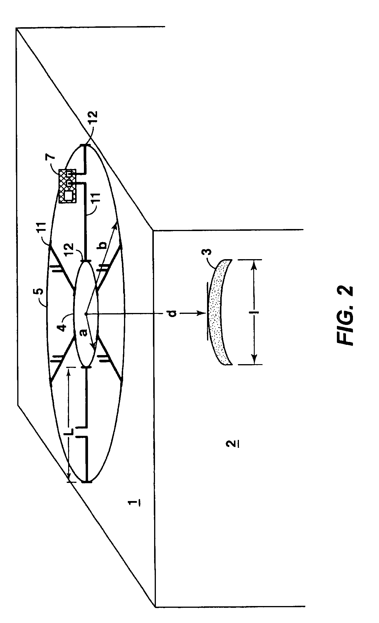
[0033]One embodiment of the layout of the apparatus used in the invention is shown in FIG. 1. In general, the invention uses the following four features that are synergistic in their combination: (1) a high-current multi-mode optimized electromagnetic source, (2) a multi-component receiver array, (3) 3-D wave-equation data processing, and (4) reservoir properties estimation and mapping. These four features will be described in turn.

[0034]In this e...


PUM


Abstract

A method for surface estimation of reservoir properties, wherein location of and average earth resistivities above, below, and horizontally adjacent to the subsurface geologic formation are first determined using geological and geophysical data in the vicinity of the subsurface geologic formation. Then dimensions and probing frequency for an electromagnetic source are determined to substantially maximize transmitted vertical and horizontal electric currents at the subsurface geologic formation, using the location and the average earth resistivities. Next, the electromagnetic source is activated at or near surface, approximately centered above the subsurface geologic formation and a plurality of components of electromagnetic response is measured with a receiver array. Geometrical and electrical parameter constraints are determined, using the geological and geophysical data. Finally, the electromagnetic response is processed using the geometrical and electrical parameter constraints to produce inverted vertical and horizontal resistivity depth images. Optionally, the inverted resistivity depth images may be combined with the geological and geophysical data to estimate the reservoir fluid and shaliness properties.

Description

[0001]This application is a divisional of application Ser. No. 10 / 798,248 filed Mar. 11, 2004, now U.S. RE 39,844, which is a reissue of U.S. application Ser. No. 09 / 656,191 filed Sep. 6, 2000 which issued as U.S. Pat. No. 6,603,313 which claims the benefit of U.S. provisional application No. 60 / 154,114 filed on Sep. 15, 1999. <?insert-start id="INS-S-00002" date="20080520" ?>Notice: More than one reissue application has been filed for the reissue of U.S. Pat. No. 6,603,313. The reissue applications are application Ser. No. 11 / 432,510 (the present application) and Ser. No. 10 / 798,248, both of which are divisional reissues of U.S. Pat. No. 6,603,313.FIELD OF THE INVENTION[0002]This invention relates generally to the field of geophysical prospecting. More particularly, the invention relates to surface measurement of subsurface geologic formation electrical resistivity. Specifically, the invention is a method of combining seismic and electromagnetic data to prospect for subsurfa...

Claims


Application Information

Patent Timeline
Patent Type & Authority Patents(United States)
IPC IPC(8): G01V3/02G01V3/08G06F19/00
CPCG01V3/12
Inventor SRNKA, LEONARD J.
Owner EXXONMOBIL UPSTREAM RES CO
Learn More